Install a HPDU In To an Oracle Rack Cabinet 1242
Install two HPDUs and two Vertical Power Strips (17KVA VPS) into the Oracle Rack Cabinet 1242.
- Unpack the HPDUs from the packaging and place them on a clean work table.
- Remove the brackets and screws from the HPDU mount shipping kit.
-
Secure the left and right mounting brackets on the front of each HPDU using
three M4 screws per bracket.
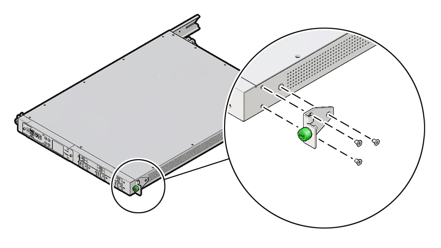
-
Secure the mounting brackets with the cage nuts on the left and right RETMA
rails at the back of the rack.
-
Using your equipment rack alignment template, or other equipment
documentation, locate the second and fifth rail holes from the
bottom.
Note - Use the cage nut insertion tool in the ship kit to install the cage nuts in the rails. - Align the cage nut with the square rail hole.
- Hook the side lip of the nut in the square rail hole.
-
Insert the tip of the cage nut insertion tool through the rail hole,
hook the other side lip of the cage nut, and lever the cage nut into
place.
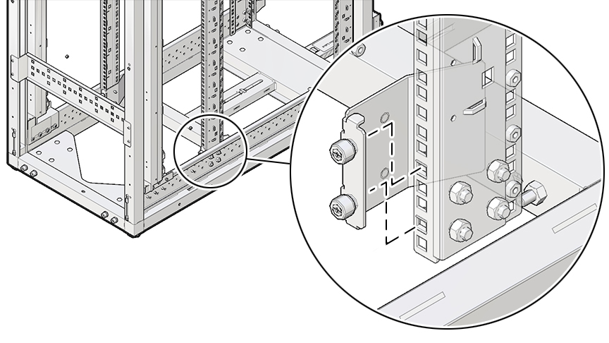
-
Using your equipment rack alignment template, or other equipment
documentation, locate the second and fifth rail holes from the
bottom.
-
Install both HPDUs.
- Slide a HPDU on the bottom of the rack from the front until the bracket catches in the square rail hole on the left and right sides of the rack.
- Verify that the HPDU slot engages the pin on the rear bracket.
- Slide the second HPDU on top of the first HPDU until it catches in the square rail hole on the left and right sides of the rack.
-
Verify that the slot of the second HPDU engages the pin on the rear
bracket.
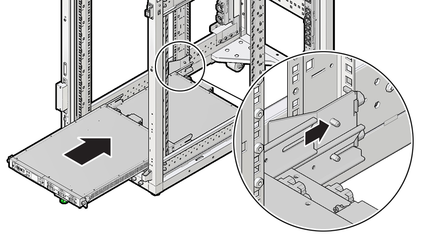
-
In the VPS shipping kit, remove the brackets and the screws and install the
VPS using the Torx T25 screwdriver.
- From the back of the cabinet, secure the top left bracket (7364703) with the stud facing the front of the rack, and the right-angle flange faces the left side of the rack, the first and third hole of the center row of holes.
- From the back of the cabinet, secure the bottom left bracket (7364704) with the stud facing the front of the rack, and the right-angle flange faces the left side of the rack, the first and third hole of the center row of holes.
- From the back of the cabinet, secure the top right bracket (7364703) with the stud facing the front of the rack, and the right-angle flange faces the right side of the rack, the first and third hole of the center row of holes, the first and third hole of the center row of holes.
-
From the back of the cabinet, secure the bottom right bracket
(7364704) with the stud facing the front of the rack, and the
right-angle flange faces the right side of the rack, starting in the
first hole of the center row of holes.
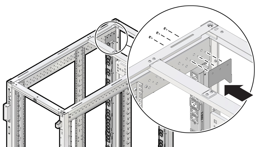
-
Install both VPS's.
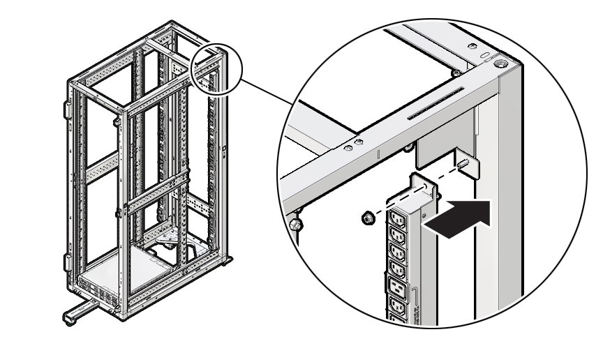
- At the back of the rack, with the PDU power cable at the bottom of the VPS, which faces the front of the rack, on the left side, align the slots at the top and bottom of the VPS with the M6 studs.
- Slide the VPS into place, and using the M10 nut driver, secure the VPS with the M6 hex nuts.
-
Snake the HPDU power cable down and forward toward the bottom HPDU,
and loop the cable to the back of the rack.
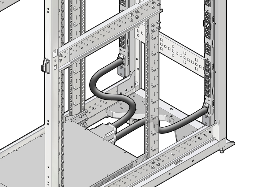
- Slide the cable into the output connector, and secure it with M4 screws using a #2 Philips screwdriver, and torque to 15 in-lbs (1.7 Nm).
-
Repeat Steps 7a-d to install the other VPS on the right side and
connect it to the top HPDU.
Note - For a 34KVA installation, connect the left VPS lower power cable to the HDPU1 connector, the left VPS upper power cable to the HPDU2 connector, the right VPS lower power cable to the HPDU3 connector, and the right VPS upper power cable to the HPDU4 connector.