Remove a Switch Chassis
This procedure can be performed only by qualified service personnel. Power down the server completely before performing this procedure.
-
Take the necessary ESD precautions.
See Prevent ESD Damage.
- Power off the server and switch off the appropriate PDU circuit breakers.
- At the front of the server, remove the power supplies.
-
At the rear of the server, remove all of these components in the order
indicated.
ComponentLinkCablesEnsure that you label the cables.SPsSP traySwitch unitsPDECBsPower module, including AC inlet strip and front indicator panel
Caution - Do not attempt to remove the chassis alone without the aide of another person or a mechanical lift.
-
At the front of the server, remove all of these components:
ComponentLinkExternal interconnectsSP interconnect
-
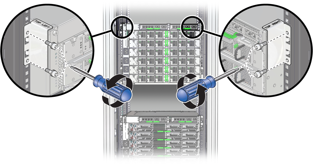
From the rear of the chassis, remove the top hold-down brackets.

-
From the front of the server, stabilize the rack using all anti-tilt mechanisms
provided.
The following steps describe how to stabilize the Sun Rack II 1242 and the Oracle Rack Cabinet 1242. If you installed a stand-alone server in your own rack, refer to the rack documentation for instructions on stabilizing the rack.
-
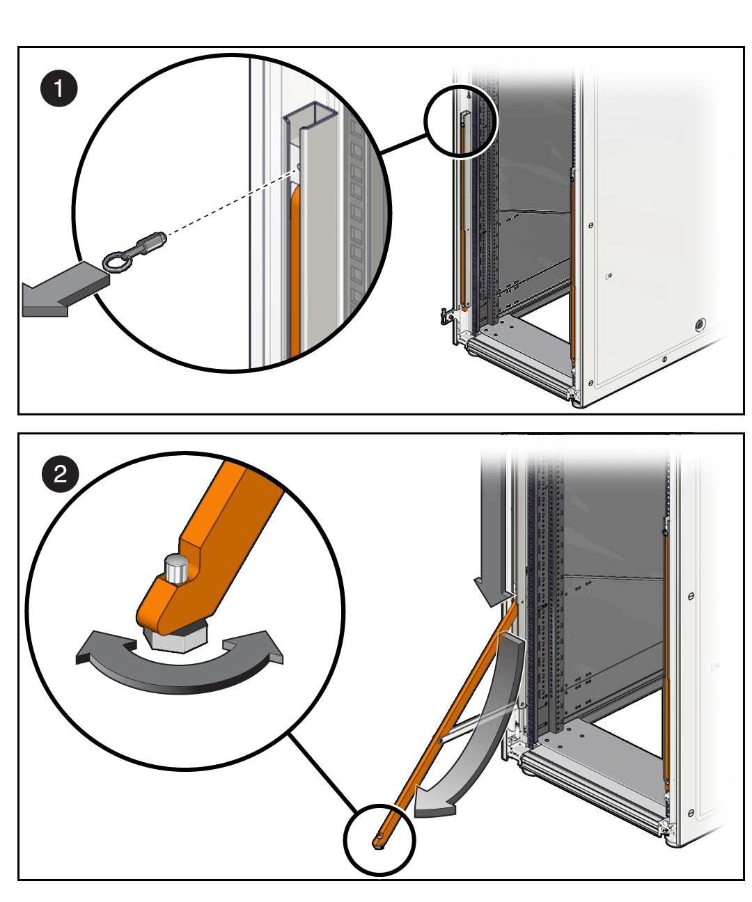
On a Sun Rack II, deploy the anti-tilt legs.

- Pull the pin to release the anti-tilt leg while pulling the leg from the bottom (panel 1).
- Loosen the leveling foot until it makes solid contact with the ground (panel 2).
-
Repeat these steps for the second leg.
Both legs must be deployed.
-
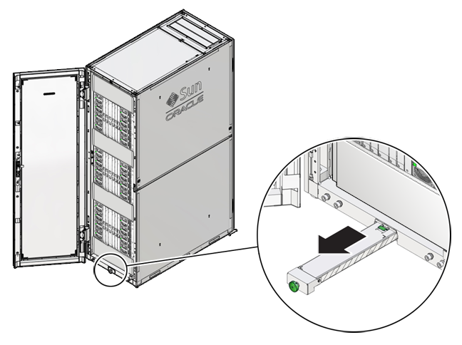
On an Oracle Rack Cabinet 1242, extend the anti-tilt bar.
-
Pull the anti-tilt bar out of the rack to the fully extended position.

-
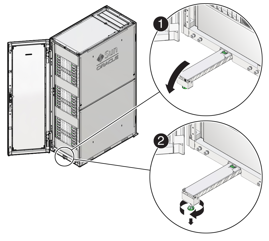
Rotate the foot of the ant-tilt bar so that it is perpendicular to the
floor.
Adjust the height of the foot so that it rests securely on the floor.

-
Pull the anti-tilt bar out of the rack to the fully extended position.
-
On a Sun Rack II, deploy the anti-tilt legs.
- Determine your next step:
- Place a mechanical lift under the chassis, and remove the screws that fasten it to the rack.
- Remove the chassis from the rack, and place it on an appropriate surface.