Remove the Front Indicator Panel Cable
This procedure can be performed only by qualified service personnel.
 | Caution - Remove AC power using the circuit breakers on the appropriate PDU before performing this procedure. |
- Determine which front indicator panel cable requires service.
-
Take the necessary ESD precautions.
See Prevent ESD Damage.
- Power off the server and switch off the appropriate PDU circuit breakers.
-
From the rear of the server, remove the SPs, and unseat the SP tray from the
impacted chassis.
See Servicing SPs and Servicing SP Trays.
-
Remove and unseat the appropriate components from the impacted chassis.
-
If the cable you are replacing is in the CMIOU chassis, remove the top four CMIOUs and unseat the lower four CMIOUs in the chassis. See Servicing CMIOUs.
-
If the cable you are replacing is in the switch chassis, remove the top three switch units and unseat the lower three switch units in the chassis. See Servicing Switch Units.
-
-
Remove the required fan modules.
If the cable you are replacing is in the CMIOU chassis, remove the four left fan modules. See Servicing Fan Modules (CMIOU Chassis).
-
Remove of the interconnect assemblies from the front of the affected
chassis.
See Servicing Internal Interconnect Assemblies, Servicing External Interconnect Assemblies (SPARC M7-16), and Servicing SP Internal Interconnect Assemblies.
- Remove the front indicator panel.
- If the cable you are replacing is in the CMIOU chassis, remove the left CMIOU chassis fan cable assembly.
-
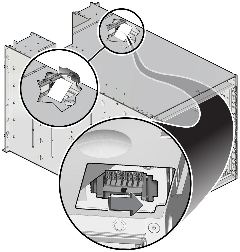
Release the Molex connector.
Reach through the hinging access door on the chassis divider floor where the SP tray slides to unlatch the Molex connector.

-
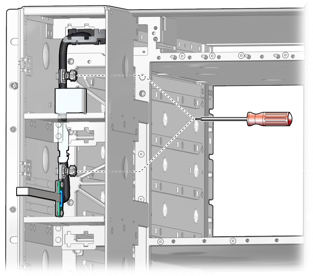
Remove the two captive screws that secure the cable to the chassis.

-
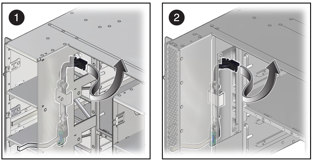
Remove the cable through the opening in the chassis.

-
If the cable you are replacing is in the CMIOU chassis, remove the cable through the opening between the fan modules and the CMIOU area (panel 1).
-
If the cable you are replacing is in the switch chassis, remove the access panel on the left side of the interconnect assembly area, and slide the cable through the opening (panel 2).
-