Install a PDU
Note - Always install the replacement PDU in the same location as the original PDU. If installed closer to the center of the rack, the PDU will interfere with the installed components. If installed nearer to the rear of the rack, the PDU will interfere with the cable management hooks and you will not be able to access the PDU circuit breakers.
-
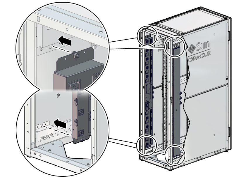
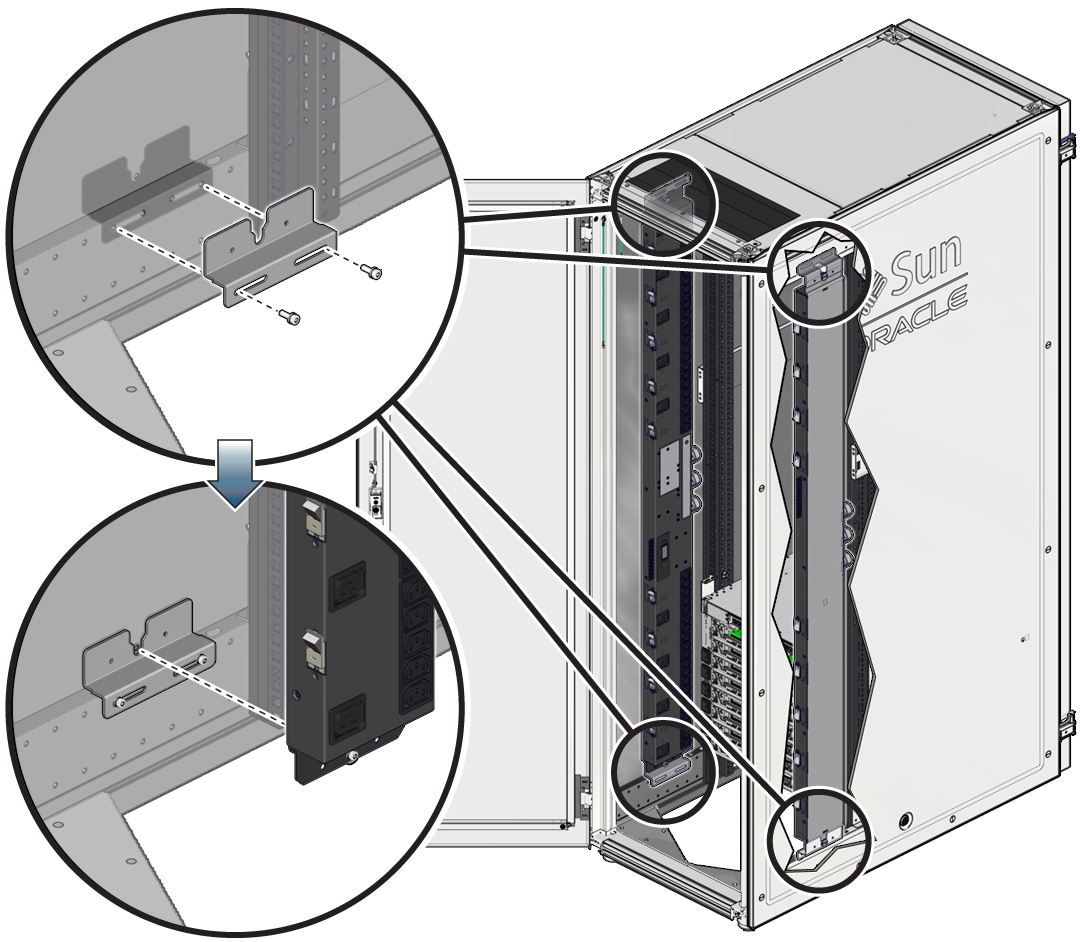
Lift up the replacement PDU and, while ensuring that the circuit breakers are
facing the rear of the rack, carefully set the replacement PDU's standoff bolts
into the top and bottom bracket keyhole slots.
Installing the PDU into an Oracle Rack Cabinet 1242:

Installing the PDU into a Sun Rack II:


Caution - You need two people to lift and secure the PDU to the rack.
The PDU is held in the rack by gravity, with the standoff bolts resting in the mounting brackets' keyhole slots.
Note - The circuit breakers must face the rear of the rack so that you can reset a breaker if one trips. -
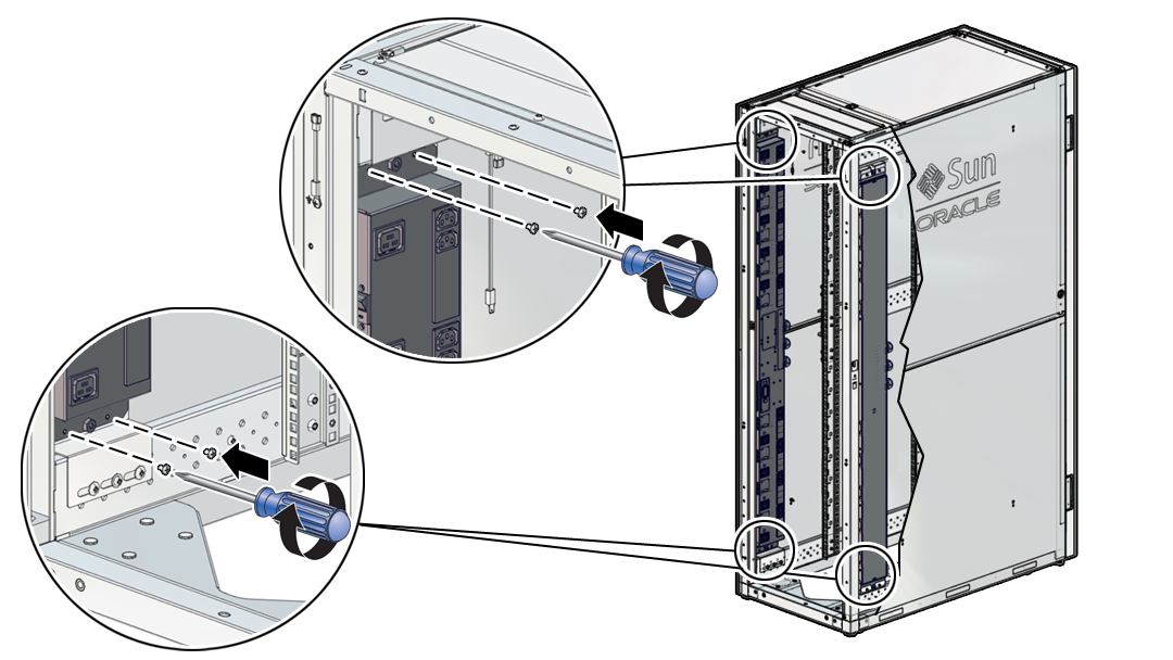
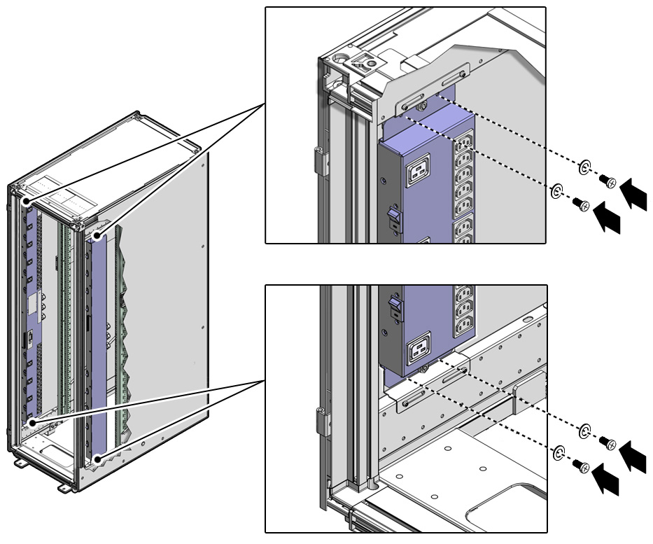
Secure the PDU to the mounting brackets.
For extra durability, secure the PDU to the mounting brackets using the shipping screws and washers (two screws and washers per bracket). If you plan to ship the rack to another location, you must secure the PDU using these shipping screws.
-
On an Oracle Rack Cabinet 1242, use a T25 Torx wrench and four M5
shipping screws to secure the replacement PDU to the mounting
brackets.

-
On a Sun Rack II, use a T25 Torx wrench and four M5 shipping screws
and washers to secure the replacement PDU to the mounting brackets.

-
On an Oracle Rack Cabinet 1242, use a T25 Torx wrench and four M5
shipping screws to secure the replacement PDU to the mounting
brackets.
-
Route the power input lead cords between the rear RETMA rail and side panel.
The replacement PDU has three power input lead cords, which you must route between the side panel and the rear RETMA rail. Route the power input lead cords either down through the bottom of the rack or up through the top of the rack, depending on where you plan to connect them to the main power source. If you are routing the cables through the bottom of the rack, refer to your rack documentation for the dimensions of the floor cutout.

Caution - Never twist, kink, or tightly bend a power input lead.
- Using tie-wraps, secure the replacement PDU input lead cables to the cable routing brackets.
-
Ensure that you have switched off every PDU circuit breaker on the replacement
PDU.
See Step 6 of Prepare a PDU for Removal.
-
Locate the replacement PDU input lead cord connectors.
Depending on how you routed the cords when you installed the PDUs, route these cords either out the bottom of the rack or out the top.
-
Connect the replacement PDU power lead cords to the facility AC power source.
If your rack contains two PDUs, ensure that each PDU is connected to different AC power source circuits, and reinstall the jumper cords in the same locations from which you removed them. For information about the installation locations for the jumper cords, refer to the SPARC M8 and SPARC M7 Servers Installation Guide.
-
Turn breakers on in the following sequence.
-
For SPARC M8-8 or SPARC M7-8 server, right PDU (PDU-B):
-
If one SPARC M8-8 or SPARC M7-8 server is installed: R8, R7, R6
-
If two SPARC M8-8 or SPARC M7-8 servers are installed: R8, R7, R6; R5, R4, R3
-
If three SPARC M8-8 or SPARC M7-8 servers are installed: R8, R7, R6; R5, R4, R3; R2, R1, R0
-
-
For SPARC M8-8 or SPARC M7-8 server, left PDU (PDU-A):
-
If one SPARC M7-8 server is installed: L2, L1, L0
-
If two SPARC M8-8 or SPARC M7-8 servers are installed: L2, L1, L0; L5, L4, L3
-
If three SPARC M8-8 or SPARC M7-8 servers are installed: L2, L1, L0; L5, L4, L3; L8, L7,L6
-
-
For a SPARC M7-16 server, right PDU (PDU-B):
-
R4, R5
-
R0, R1, R2
-
R6, R7, R8
-
-
For a SPARC M7-16 server, left PDU (PDU-A):
-
L5, L4
-
L8, L7, L6
-
L2, L1, L0
-
where R indicates the right PDU from the rear of the server (PDU B), L indicates the left PDU from the rear of the server (PDU A), and the number represents the PDU group number.
Note - As soon as PDU circuit breakers are switched on, standby power is applied, and the SP boots.See Switch on PDU Circuit Breakers for the order to switch the breakers.
-
-
Restart the server.
-> start /System
- Return the replaced component to Oracle.