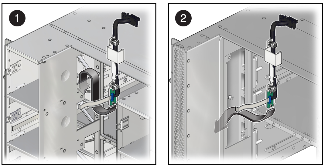
Install the Front Indicator Panel Cable
-
Install the cable through the opening in the chassis and secure the Molex
connector.

-
If the cable you are replacing is in the CMIOU chassis, from inside the CMIOU area, feed the cable through the area behind the fan module bays (panel 1).
-
If the cable you are replacing is in the switch chassis, feed the cable through the area where the access panel on the left side of the interconnect assembly was removed (panel 2).
-
- Reinstall the two captive screws that secure the cable to the chassis.
- If the cable you are replacing is in the switch chassis, reinstall the access panel on the left side of the interconnect assembly area.
- If the cable you are installing is in the CMIOU chassis, reinstall the left CMIOU chassis fan cable assembly.
- Reinstall the front indicator panel.
-
Reinstall the interconnect assemblies in the front of the affected
chassis.
Note - You must return interconnect assemblies to their original slots in the server.See Servicing Internal Interconnect Assemblies, Servicing External Interconnect Assemblies (SPARC M7-16), and Servicing SP Internal Interconnect Assemblies.
-
Reinstall the removed fan modules.
If the cable you are replacing is in the CMIOU chassis, reinstall the four left fan modules. See Servicing Fan Modules (CMIOU Chassis).
-
Reinstall and reseat the required components from the impacted chassis.
-
If the cable you are installing is in the CMIOU chassis, reinstall the top four CMIOUs and reseat the lower four CMIOUs. See Servicing CMIOUs.
-
If the cable you are installing is in the switch chassis, reinstall the top three switch units and reseat the lower three switch units. See Servicing Switch Units.
-
-
Reseat the SP tray and reinstall the SP in the server.
See Servicing SP Trays and Servicing SPs.
Note - If the SP is configured to synchronize with a network time server using the Network Time Protocol, the Oracle ILOM clock will be reset as soon as the server is powered on and connected to the network.See Install an SP or SPP.
- Switch on the appropriate PDU circuit breakers and power on the server.
- Verify that the fault has been cleared and the replaced component is operational.
- Return the replaced component to Oracle.