Install an SP Internal Interconnect Assembly
 | Caution - If the SP internal interconnect you are installing has stirrup-shaped leaf springs that hold the inner and outer horizontal connectors in place, handle the interconnect with care to avoid damaging the floating connector housings. These housings can become damaged if they loosen and catch on the chassis, which can impact your ability to install or remove the interconnect. If you notice that these springs or the connectors are damaged, do not install the interconnect into the chassis. |
-
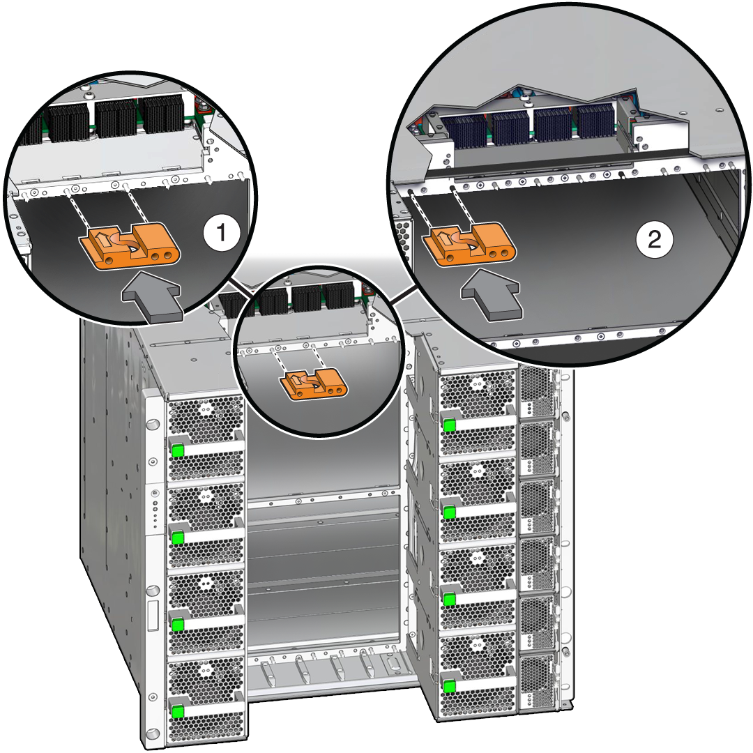
Insert the guide pin shield to avoid damaging the connector pins on the rear
of the SP internal interconnect assembly.

- If you are installing an SP internal interconnect assembly in the CMIOU chassis, place the guide pin shield as shown in panel 1.
- If you are installing an SP internal interconnect assembly in the switch chassis, place the guide pin shield as shown in panel 2.
-
From the front of the server, carefully slide the SP internal interconnect
assembly into the chassis.

Caution - The small connector pins on the back of the assembly are susceptible to damage. Align the assembly in the chassis and install the assembly slowly to avoid bending or otherwise damaging them.
-
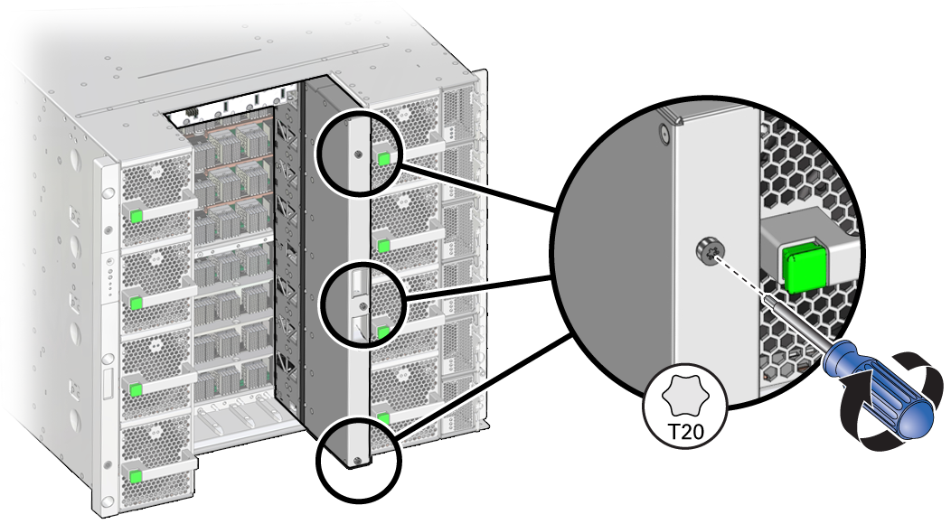
Secure the SP internal interconnect assembly to the chassis.
-
Tighten the captive screws on the face of the assembly.

-
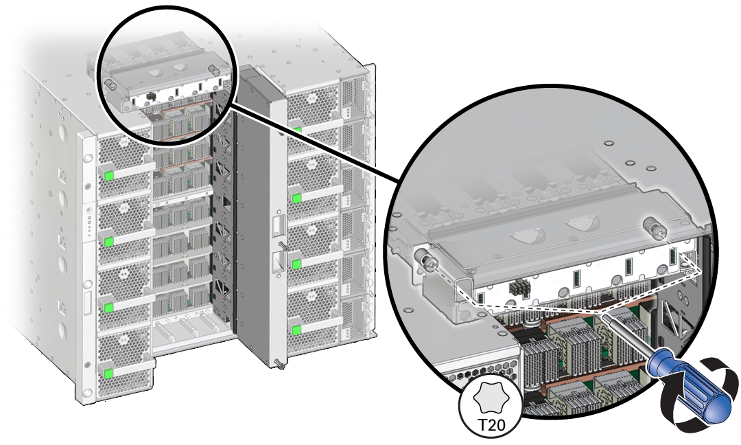
Use a T20 driver to install the screws in the white, horizontal strip
that extends to the left of the SP internal interconnect
assembly.

-
Tighten the captive screws on the face of the assembly.
-
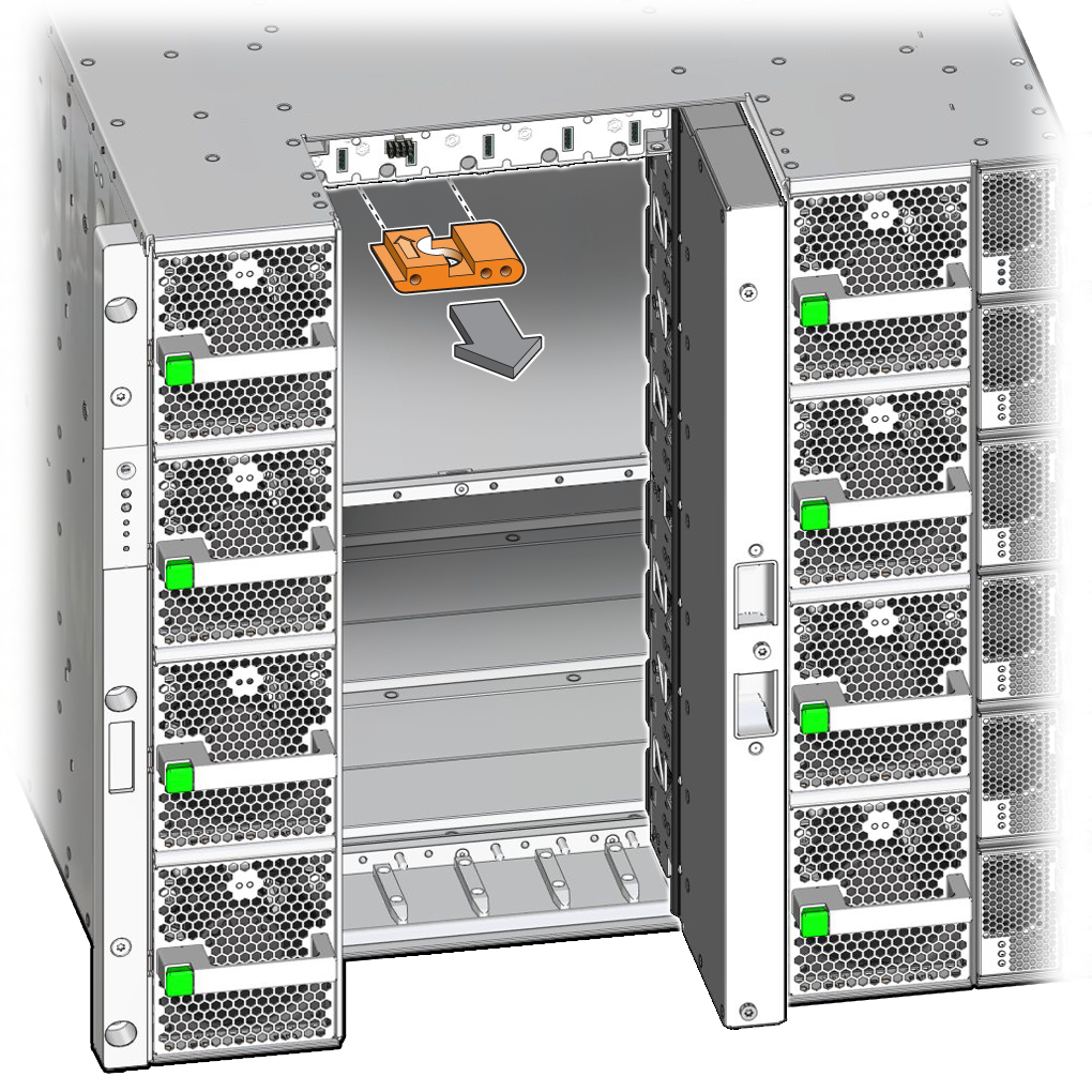
Remove the guide pin shield.

-
Complete the following steps to reinstall components you removed to service
the assembly.
-
Reinstall all of the interconnect assemblies that you removed.
See Servicing Internal Interconnect Assemblies or Servicing External Interconnect Assemblies.
-
Reseat all CMIOUs or switch units from the impacted chassis.
See Reseat a CMIOU or Reseat a Switch Unit.
-
From the rear of the server, reinstall the SP tray and the SPs.
See Servicing SP Trays and Servicing SPs.
-
Reinstall all of the interconnect assemblies that you removed.
- Switch on the appropriate PDU circuit breakers and power on the server.
- Verify that the fault has been cleared and the replaced component is operational.