4.1 PCIe, PCI-X, and XAUI Card Configuration Reference
This section describes suggested PCI/XAUI card features and configurations. See Rear Panel Features and Connector Locations for back panel locations of the PCI slots.
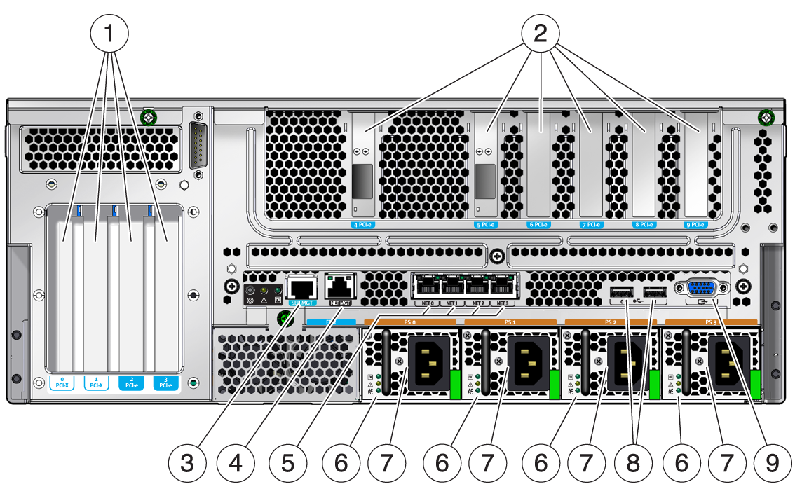
Figure 4-1 Rear Panel Features and Connector Locations

Figure Legend
1 PCI Slots 0-3: left to right: PCI-X Slot 0 (25 W maximum load), PCI-X Slot 1 (25 W maximum load), PCIe Slot 2 (75 W maximum load), PCIe Slot 3 (75 W maximum load) Note - Only one 75 W PCIe card can be installed in the server at one time. It is suggested to install the 75 W card in Slot 2 for better cooling.
2PCI (or XAUI) Slots 4-6 and PCIe Slots 7-9: left to right: PCIe or XAUI Slot 4 (15 W maximum load), PCIe or XAUI Slot 5 (15 W maximum load), PCIe Slot 6 (15 W maximum load), PCIe Slot 7 (15 W maximum load), PCIe Slot 8 (15 W maximum load), PCIe Slot 9 (15 W maximum load)
3Service Processor Serial Management Port
4ServIce Processor Network Management Port
5Gigabit Ethernet ports left to right: NET0, NET1, NET2, NET3
6Power Supply LEDs (each PSU) top to bottom: Output On LED (Green), Service Required LED (Amber), Input Power OK LED (Green)
7Power supplies (PSs): left to right: PS 0, PS 1, PS 2, PS 3
8USB ports left to right: USB2, USB3
9TTYA serial port
4.1.1 PCI Cards on the PCI Auxilliary Board
Slot 0 and Slot 1 are 133MHZ PCI-X slots and support form factor PCI-X cards. The maximum power for each slot is 25 Watts.
Slot 2 and Slot 3 are x8 PCIe slots that have x16 mechanical connectors. These slots support form factor PCIe cards, and support the highest power 75 Watt PCIe card. However, only one 75 Watt PCIe card in either slot can be installed in the server at one time.
Tip - Install the 75 Watt card in Slot 2 for better cooling.
4.1.2 PCI Cards on the PCI Mezzanine Assembly
PCIe Slots 4-9 are x8 PCIe slots and support low profile PCIe cards and Max power for each slot is 25 Watts. PCIe Slot 4 and PCIe Slot 5 are combination slots with XAUI4 and XAUI5. The following restrictions apply:
If a XAUI card is installed in the XAUI4 slot, the PCIe Slot 4 cannot be used, and the Ethernet Port 1 on the motherboard will be disabled.
If a XAUI card is installed in the XAUI5 slot, the PCIe Slot 5 cannot be used and the Ehternet Port 0 on the motherboard will be disabled.
4.1.3 High Bandwidth PCIe Card Installation
To balance the PCIe bus bandwidth from the upstream of the PCIe buses, it is suggested to limit the numbers of high bandwidth PCIe cards installed in the server. It is also suggested to install the high bandwidth PCIe cards in the assigned slots. The following are two examples:
Example 1 – If one or two XAUI cards are installed in the server, it is suggested to install two high bandwidth PCIe cards: one in Slot 2 and in Slot 8.
Example 2 – If there are no XAUI cards installed in the server, it is suggested to install four high bandwidth PCIe cards: one in Slot 2, 4, 8, and 9.