Sun Netra T5440 Server

Exit Print View

Updated: September 2015


1.3 Using LEDs to Identify the State of Devices

The server provides the following groups of LEDs:

These LEDs provide a quick visual check of the state of the system.

1.3.1 Front and Rear Panel LEDs

The seven front panel LEDs (Location of the Bezel Server Status and Alarm Status Indicators) are located in the upper left corner of the server chassis. Three of these LEDs are also provided on the rear panel (Rear Panel Connectors, LEDs, and Features on the Sun Netra T5440 Server).

Figure 1-2  Location of the Bezel Server Status and Alarm Status Indicators
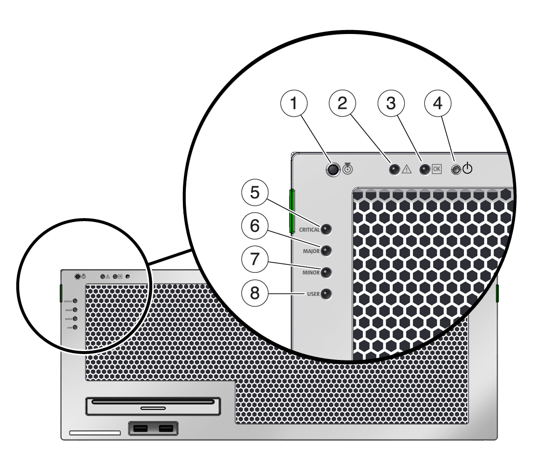
image:Figure showing the the location of the server and alarm status indicators on the front bezel

Figure Legend

1 Locator LED and Button

2Fault LED

3Activity LED

4Power OK LED

5User (amber) Alarm Status Indicator

6Minor (amber) Alarm Status Indicator

7Major (red) Alarm Status Indicator

8Critical (red) Alarm Status Indicator

Figure 1-3  Rear Panel Connectors, LEDs, and Features on the Sun Netra T5440 Server
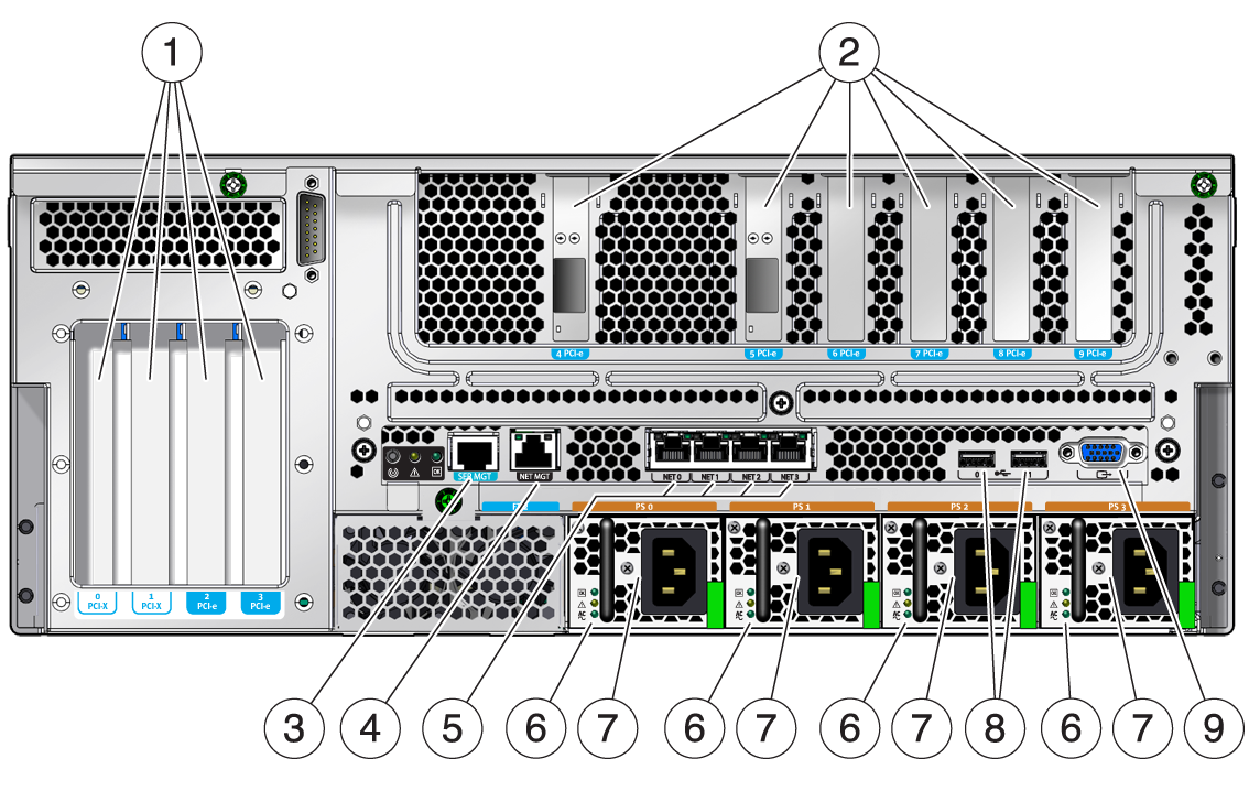
image:Figure showning the rear panel connectors, LEDs, and features

Figure Legend

1 PCI Slots 0-3: left to right: PCI-X Slot 0 (25 W maximum load), PCI-X Slot 1 (25 W maximum load), PCIe Slot 2 (25 W maximum load), PCIe Slot 3 (25 W maximum load)

2PCI (or XAUI) Slots 4-9: left to right: PCIe or XAUI Slot 4 (15 W maximum load), PCIe or XAUI Slot 5 (15 W maximum load), PCIe Slot 6 (15 W maximum load), PCIe Slot 7 (15 W maximum load), PCIe Slot 8 (15 W maximum load), PCIe Slot 9 (15 W maximum load)

3Service Processor Serial Management Port

4Service Processor Network Management Port

5Gigabit Ethernet Ports left to right: NET0, NET1, NET2, NET3

6Power Supply 0 LEDs top to bottom: Output On LED (green), Service Required LED (yellow), Input Power OK LED (green)

7Power Supplies (PSs): left to right: PS 0, PS 1, PS 2, PS 3

8Rear left and right USB ports

9TTYA Serial Port

Front and Rear Panel LEDs  lists and describes the front and rear panel LEDs.

Table 1-2  Front and Rear Panel LEDs 
LED
Location
Color
Description
Locator LED and Butto n
Front upper left and rear center
White
Enables you to identify a particular server. The LED is activated using one of the following methods:
  • Issuing the setlocator on or off command.

  • Pressing the button to toggle the indicator on or off.

This LED provides the following indications:
  • Off – Normal operating state.

  • Fast blink – The server received a signal as a result of one of the preceding methods.

F ault LED
Front upper left and rear center
Amber
If on, indicates that service is required. The ALOM CMT CLI showfaults command provides details about any faults that cause this indicator to be lit.
A ctivity LED
Front upper left
Green
  • On – Drives are receiving power. Solidly lit if drive is idle.

  • Flashing – Drives are processing a command.

  • Off – Power is off.

Power Button
Front upper left
Turns the host system on and off. This button is recessed to prevent accidental server power-off. Use the tip of a pen to operate this button.
Ala rm:Critical LED
Front left
Red
Indicates a critical alarm. Refer to the server administration guide for a description of alarm states.
Alarm:Major LED
Front left
Red
Indicates a major alarm.
Alarm:Minor LED
Front left
Amber
Indicates a minor alarm.
Alarm :User LED
Front left
Amber
Indicates a user alarm.
Power OK LED
Rear center
Green
The LED provides the following indications:
  • Off – The system is unavailable. Either the system has no power or ILOM is not running.

  • Steady on – Indicates that the system is powered on and is running it its normal operating state.

  • Standby blink – Indicates that the service processor is running while the system is running at a minimum level in Standby mode, and is ready to be returned to its normal operating state.

  • Slow blink – Indicates that a normal transitory activity is taking place. The system diagnostics might be running, or that the system might be booting.

1.3.2 Hard Drive LEDs

The hard drive LEDs (Hard Drive LEDs and Hard Drive LEDs ) are located on the front of each hard drive that is installed in the server chassis.

Figure 1-4  Hard Drive LEDs

image:Figure showing the hard drive LEDs

Figure Legend

1 OK to Remove

2Fault

3Activity

Table 1-3  Hard Drive LEDs 
LED
Color
Description
OK to Remove
Blue
  • On – The drive is ready for hot-plug removal.

  • Off – Normal operation.

Faul t
Amber
  • On – The drive has a fault and requires attention.

  • Off – Normal operation.

Activity
Green
  • On – The drive is receiving power. Solidly lit if drive is idle.

  • Flashing – The drive is processing a command.

  • Off – Power is off.

1.3.3 Power Supply LEDs

The power supply LEDs (Power Supply LEDs and Power Supply LEDs ) are located on the rear of each power supply.

Figure 1-5  Power Supply LEDs
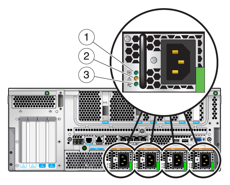
image:Figure showing the power supply LEDs

Figure Legend

1 Power OK power supply LED

2Fault power supply LED

3Input OK power supply LED

Table 1-4  Power Supply LEDs 
LED
Color
Description
Power OK
Green
  • On – Normal operation. DC output voltage is within normal limits.

  • Off – Power is off.

Fault
Amber
  • On – Power supply has detected a failure.

  • Off – Normal operation.

Input OK
Green
  • On – Normal operation. Input power is within normal limits.

  • Off – No input voltage, or input voltage is below limits.

1.3.4 Ethernet Port LEDs

The ILOM management Ethernet port and the four 10/100/1000 Mbps Ethernet ports each have two LEDs, as shown in Ethernet Port LEDs and described in Ethernet Port LEDs .

Figure 1-6  Ethernet Port LEDs

image:Figure showing the Ethernet LEDs

Figure Legend

1 Link/Activity indicator LED (Same location for all Ethernet ports)

2Speed indicator LED (Same location for all Ethernet ports)

Table 1-5  Ethernet Port LEDs 
LED
Color
Description
Left LED
Green
Link/Activity indicator:
  • Steady On – a link is established.

  • Blinking – there is activity on this port.

  • Off – No link is established.

Right LED
Amber or Green
Speed indicator:
  • Amber On – The link is operating as a Gigabit connection (1000-Mbps)

  • Green On – The link is operating as a 100-Mbps connection.

  • Off – The link is operating as a 10/100-Mbps connection.


Note - The NET MGT port operates only in 100-Mbps or 10-Mbps so the speed indicator LED can be green or off (never amber).