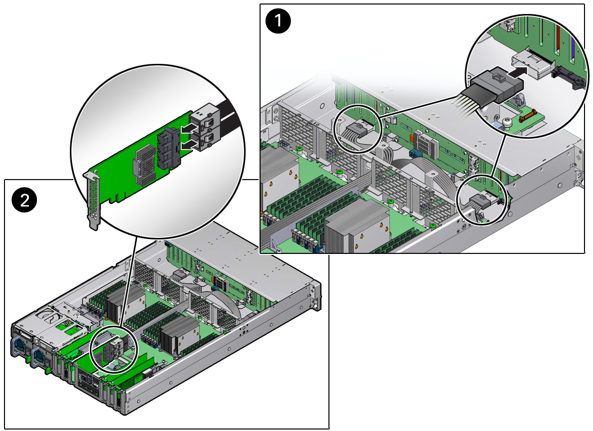
Install NVMe Cables
-
Install the NVMe cables between the front storage drive backplane and the
Oracle PCIe NVMe switch card in PCIe slot 3.
Route the NVMe cable bundle through the chassis mid-wall and via the cable trough between the fan modules and processors.
-
Reconnect the NVMe cables to the front storage drive backplane [1].
Plug each cable into its connector until you hear an audible click.
Note - The following figure shows NVMe cables being installed in the twenty-four drive system configuration. If you are installing NVMe cables in an eight-drive system configuration, your front disk backplane NVMe connector locations will be different.
-
Reconnect the NVMe cables to the Oracle PCIe NVMe switch card in slot 3
[2].
Plug each cable into its connector until you hear an audible click. See also Install a PCIe Card.
Use the following table to ensure proper NVMe cable connections.
Note - Each NVMe cable contains a matching label that corresponds to the port on the Oracle PCIe NVMe switch card. For example, the NVMe cable labeled 0,1 plugs into Oracle PCIe NVMe switch card port 0,1, and the cable labeled 2,3 plugs into Oracle PCIe NVMe switch card port 2,3.System Disk ConfigurationDisk Backplane Cable ConnectorOracle PCIe NVMe Switch Card Port Cable ConnectorCable Part NumberEight storage driveA2,37089783Eight storage driveB0,17089783Twenty-four storage drivesA2,37089784Twenty-four storage drivesB0,17089784 -
Return the server to operation.
- Depending on your server's storage drive configuration, do one of the following:
- Lower the air baffle to the installed position.
-
Install the fan modules and close the fan assembly door.
See Install a Fan Module.
- Install the server top cover.
- Return the server to the normal rack position.
-
Reconnect the power cords to the power supplies, and power on the
server.
See Reconnect Power and Data Cables and Power On the Server. Verify that the power supply AC OK LED is lit.