Install the Motherboard Assembly
- Attach an antistatic wrist strap to your wrist, and then to a metal area on the chassis.
-
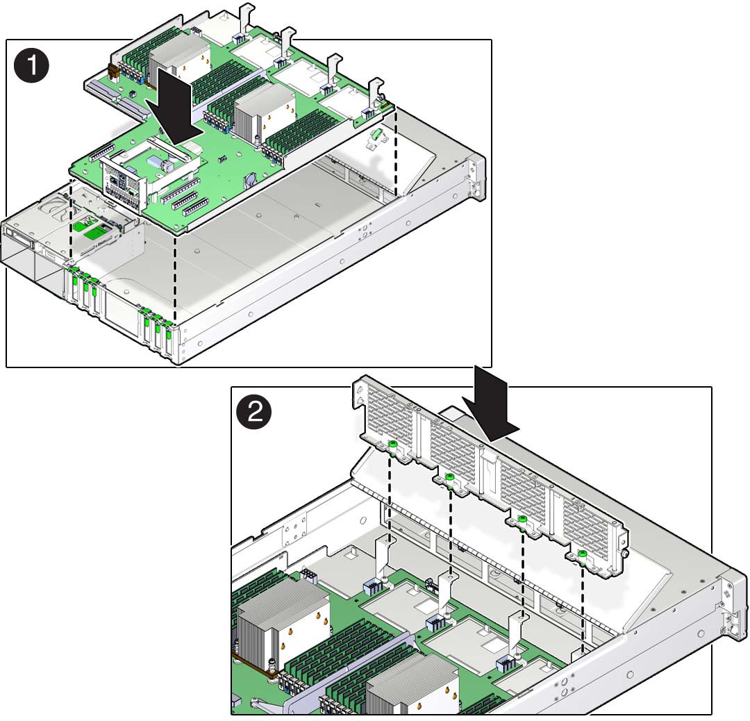
Carefully lift and place the motherboard assembly into the chassis
[1].
Tilt the motherboard to the right side to fit under the power supply assembly, level the motherboard and place it into the server chassis, then slide it to the rear of the server to engage the raised standoffs.

-
Install the mid-wall into the chassis.
- Lift and place the mid-wall into the chassis [2].
-
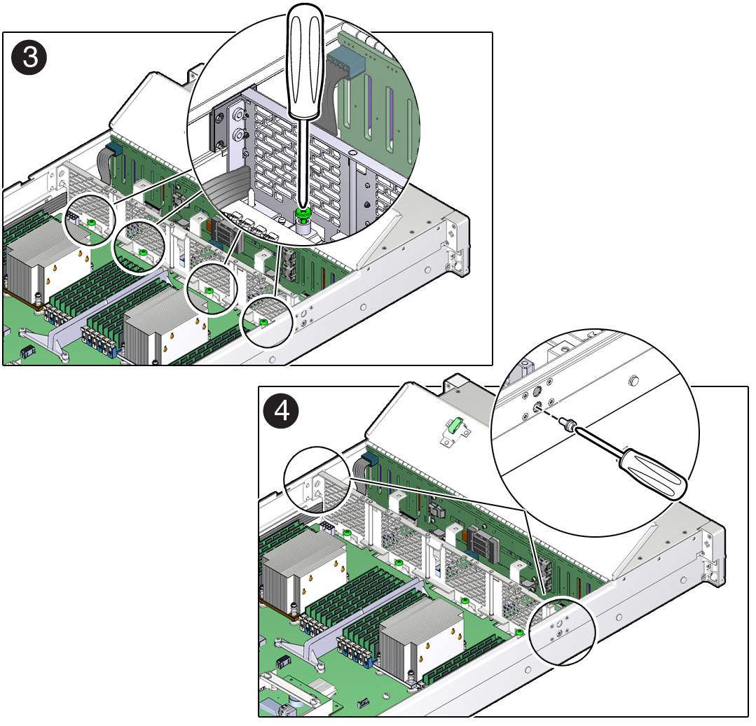
Using a No. 2 Phillips screwdriver, tighten the four green captive
screws that secure the mid-wall to the bottom of the chassis
[3].

- Using a hex/flat head screwdriver, insert and tighten the screw on each side of the chassis to secure the mid-wall in the chassis [4].
-
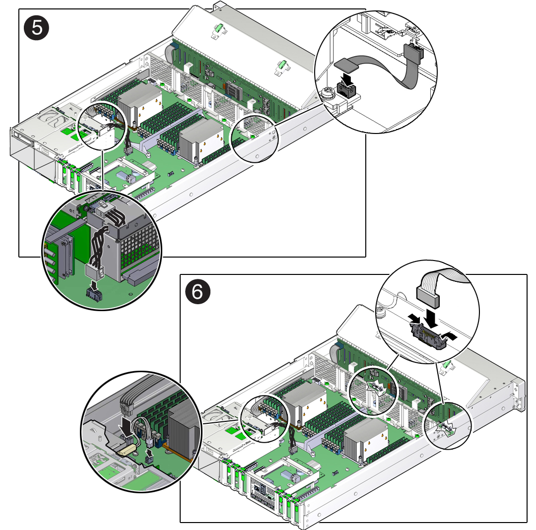
Reconnect the power cable to the motherboard from the rear storage drive
backplane [5].
See Servicing the Front and Rear Storage Drive Backplanes (FRU).
-
Reconnect the auxiliary signal cable to the motherboard from the front
storage drive backplane [5].
See Servicing the Front and Rear Storage Drive Backplanes (FRU).

- Reconnect the ribbon cables from left and right LED/USB indicator modules to the motherboard [6].
-
Reconnect the power cable to the motherboard from the front storage drive
backplane [6].
See Servicing the Front and Rear Storage Drive Backplanes (FRU).
- Reconnect the server intrusion switch cable to the motherboard [6].
-
If the server has a DVD drive, reconnect the DVD drive cable.
To reconnect the DVD drive cable, carefully guide it through the chassis mid-wall and reconnect it to the motherboard SATA connector.
-
Reinstall the following components:

Caution - When reinstalling power supplies, it is important to reinstall them into the slots from which they were removed during the motherboard removal procedure; otherwise, the server key identity properties (KIP) data might be lost. When a server requires service, the KIP is used by Oracle to verify that the warranty on the server has not expired. For more information on KIP, see FRU Key Identity Properties (KIP) Automated Update.
-
Power supplies
-
PCIe cards
See Install a PCIe Card.
-
NVMe cables (if present)
See Install NVMe Cables.
-
SAS storage drive cables
-
Fan modules
See Install a Fan Module.
-
-
Install the air baffle.
Install the air baffle by placing it into the server. Leave the air baffle in an upright position in preparation for installing the Oracle Storage 12 Gb/s SAS PCIe RAID HBA card.
-
Install the Oracle Storage 12 Gb/s SAS PCIe RAID HBA card and its
associated super capacitor.
See Install the Oracle Storage 12 Gb/s SAS PCIe RAID HBA Card.
-
Return the server to operation.
- Install the server top cover.
- Return the server to the normal rack position.
-
Reconnect the power cords to the power supplies, and power on the
server.
See Reconnect Power and Data Cables and Power On the Server. Verify that the power supply AC OK LED is lit.
Note - IMPORTANT: After replacing the motherboard, you might need to manually program the product serial number (PSN) into the new motherboard. This is necessary because the motherboard is a secondary member of a select group (or quorum) of components for maintaining the PSN for service entitlement, and if you replace more than one of the quorum members during any given service procedure, a secondary quorum member might need to be programmed with the PSN.