Install a Data Cable
Installing a single data cable is a hot-swap operation. If you are installing all data cables at one time, the switch should be in a powered off state.
-
Consider your first steps.
-
If you are replacing a data cable, remove the faulty or obsolete data
cable first, then return to Step 3 of this task.
See Remove a Data Cable.
- If you are installing a replacement cable, go to Step 3.
- If you are adding an additional data cable, see Preparing for Service, and then go to Step 2.
- If you are installing a data cable as part of a switch installation task, go to Step 6.
-
If you are replacing a data cable, remove the faulty or obsolete data
cable first, then return to Step 3 of this task.
-
If you have not already done so, loosen the thumbscrews and remove the cover
for the CMB.
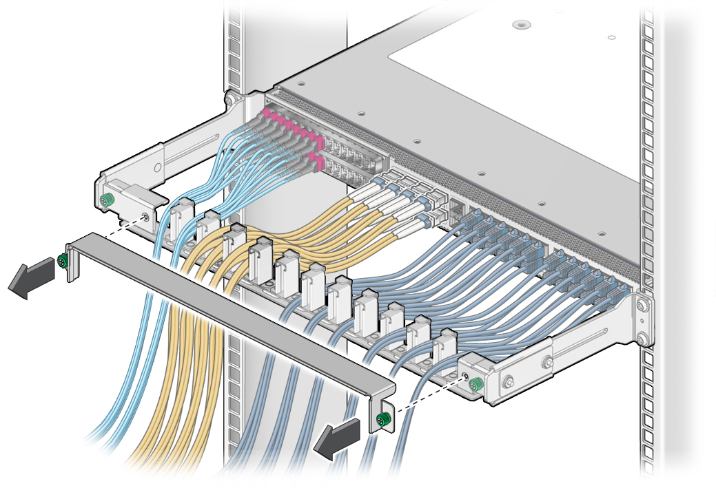
- If you are installing an optical fiber SFP+ cable that needs assembly, assemble the cable now.
-
Connect the replacement cable to the remote location, and route it to the
switch.
See the Oracle InfiniBand Switch IS2-46 Installation Guide, routing data cables.
- Bring the cable to the switch and remove its protective cap, if installed.
-
Consider your next steps.
If you are installing all cables as part of a switch replacement, start with the RJ-45 cables.
-
Install an RJ-45 cable.
-
Align the RJ-45 connector to where it will install into the
receptacle.
The tab on the connector is up for the upper row of receptacles and down for the lower row of receptacles.
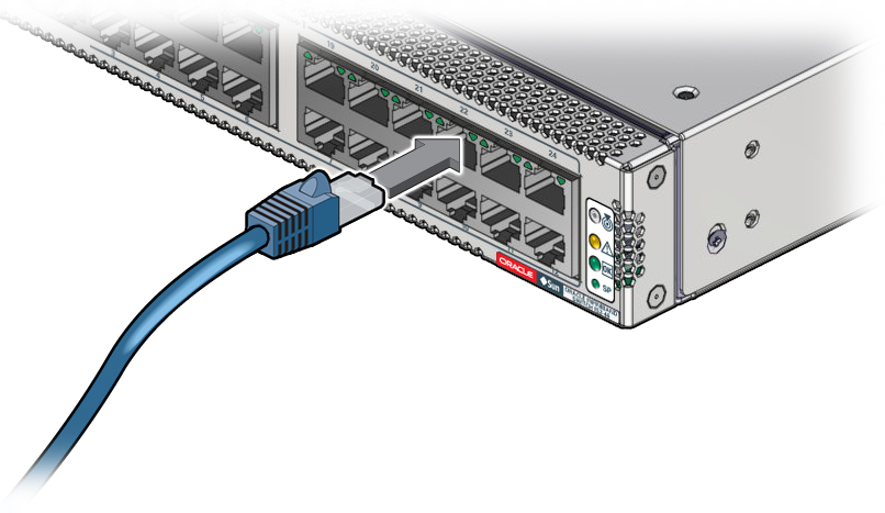
- Firmly press the RJ-45 connector into the receptacle until you hear a click.
- Go to Step 10.
-
Align the RJ-45 connector to where it will install into the
receptacle.
-
Install an SFP+ cable.
-
Align the SFP+ connector to where it will install into the
receptacle.
The product label on the connector is up for the upper row of receptacles and down for the lower row of receptacles.
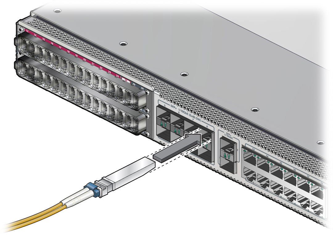
- Slowly move the connector in and continue to push until you feel a detent.
- Go to Step 10.
-
Align the SFP+ connector to where it will install into the
receptacle.
-
Install a PrizmMT cable.
Note - PrizmMT receptacles labeled 1 through 26 are for 4x magenta-colored housing PrizmMT cables. PrizmMT receptacles labeled 27 through 30 are for 12x black-colored housing PrizmMT cables.-
Remove any filler plug (if installed) from the PrizmMT receptacle
where you are installing the cable and visually inspect the receptacle.
The receptacle should be clean and free of dirt or debris. If the receptacle is dirty, clean it. See (Optional) Clean the PrizmMT Receptacle or Connector Ferrule.
-
Remove the protective cap from the cable connector and visually
inspect the connector.
The connector should be clean and free of dirt or debris. If the connector is dirty, clean it. See (Optional) Clean the PrizmMT Receptacle or Connector Ferrule.
-
Align the PrizmMT connector to where it will connect.
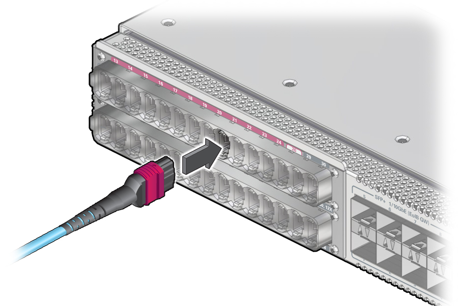
- Firmly press the PrizmMT connector into the receptacle until you feel a detent.
-
Remove any filler plug (if installed) from the PrizmMT receptacle
where you are installing the cable and visually inspect the receptacle.
- Lay the cable into the CMB.
- If you installed a data cable as part of a switch configuration, return to that task.
- Repeat Step 3 through Step 10 for any additional cables to be installed.
-
Replace the cover for the CMB and tighten the thumbscrews.
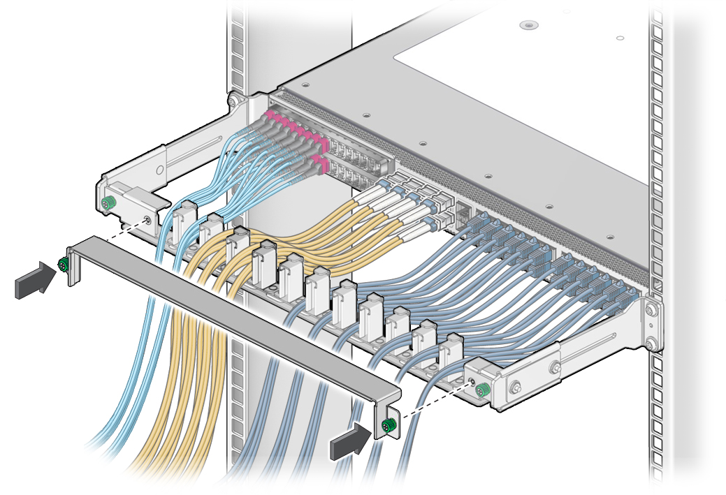
- Consider your next steps.
-
Verify the data cable.
See Verify a Data Cable.