Replace the Motherboard (FRU)
This section provides instructions for replacing the server motherboard.
When servicing the components in this section, unplug the AC power cords and use ESD protection.
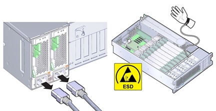
To replace the motherboard, remove and retain internal motherboard-mounted components.
Before You Begin
-
For serviceability considerations, see Component Serviceability.
-
To complete this procedure, you need:
-
Alcohol wipes
-
Thermal compound
-
- Prepare the server for service.
- Remove the SP card.
-
Remove all PCIe cards from the server, disconnecting any external or internal cables and
taking care to note their cable arrangement and slot assignments.
See Remove a PCIe Card.
The slot population on the replacement motherboard needs to match the population on the failed board.
-
If the server has only two CPUs, remove the air baffle.
The air baffle simply lifts straight up and out of the system. It is not attached to anything.
- Remove all memory riser cards.
-
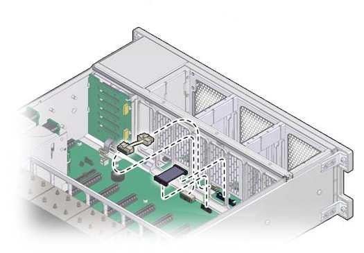
Disconnect the fan board power and data cables from motherboard.
These cables do not need to be removed from the system and can remain plugged into the fan board. However, care must be taken not to damage these cables when removing or inserting the motherboard.
-
Disconnect the SAS/SATA cables and any NVMe cables (if present) from the disk
backplane.
See Replace the NVMe Switch Card Cables (FRU) and Replace the SAS 12 Gb/s Internal HBA SAS Cables (FRU).
- Remove the ESM module from its dual lock strip on the chassis.
-
Remove the air divider.
The divider is mounted to the power supply side wall using two tabs, which are inserted into slots in the side wall.
-
Lift the disconnected cables (SAS, NVMe, ESM) out of the slot in the air divider [B in the
illustration below] that routes them into the disk backplane area.
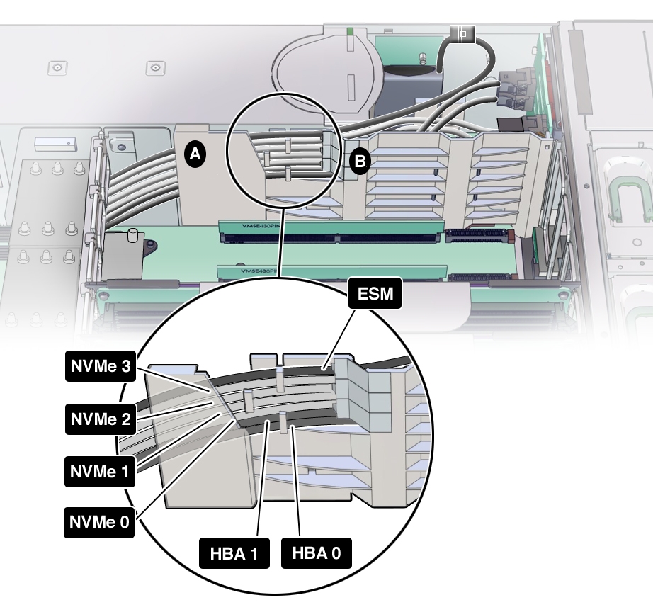
- Then slid each cable up and out of the three air divider cable clips so that they are loose, and gently place them on the memory riser side of the air divider.
- Slide the air divider upwards so its tabs clear the slots in the power supply side wall.
- Lift the air divider out of the system, leaving the cables (SAS, NVMe, ESM).
-
Lift the disconnected cables (SAS, NVMe, ESM) out of the slot in the air divider [B in the
illustration below] that routes them into the disk backplane area.
-
To remove the SAS, NVMe (if present), and ESM cables from the system, carefully thread each
one between the CPU 0 heatsink and the power supply side wall, and out towards the front of the
system.
Some of the cable connectors only fit one way between the CPU 0 heat sink and power supply side wall as the space is very narrow.
- Remove the data and power cables for the disk backplane.
-
Remove the power supply cable from the motherboard.
Connected to the motherboard from the power supply backplane.
-
Remove any USB flash drives attached to the internal USB ports.
Make note of the ports for each USB flash drive.
- Remove the heatsinks and CPUs from the motherboard.
- Remove the system battery.
-
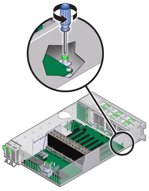
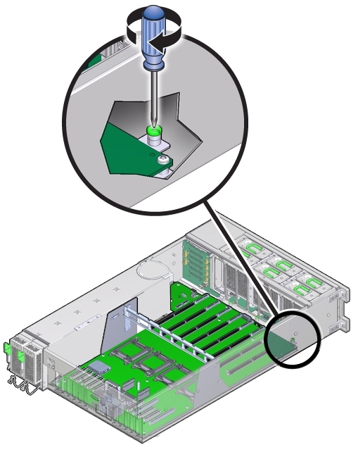
Loosen the green captive screw that secures the motherboard to the chassis.
The screw is located at the left front corner of the motherboard behind FM3.
- Ensure there are no cables left attached to the motherboard, and that there are no cables draped inside of the chassis that might be in the way of removing the motherboard.
-
Holding the metal memory riser card guide (over the CPU sockets) and the metal handle above
the SP card slot, slide the motherboard toward the front of the server. If extra force is required
to break loose the fit around the motherboard rear connectors and the chassis, use the rear handle
(by the SP connector) and not the memory riser guide, as it might bend.
The motherboard is mounted to a metal plate. The plate has eight keyed slots that align with eight mushroom head standoffs mounted to the bottom of the chassis. The standoffs lock the motherboard and plate assembly to the chassis. To unlock the assembly, you need to slide the assembly toward the front of the server.
-
Once the motherboard has been slid forward as far as it will go, lift the front end of the
motherboard while gently sliding it away from the back of the server, ensuring that the Locator
indicator light pipe extension piece slides out of its hole at the back of the chassis.
Note - If the Locator indicator light pipe extension detaches during removal, ensure that you retrieve it from the server. The extension is a clear plastic piece that transmits light and allows you to activate the Locator indicator switch from the back of the server. It is needed for the replacement motherboard.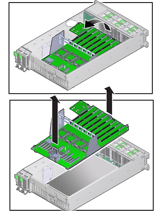
- To remove the motherboard, slowly guide it up and out of the server.
-
Lift the replacement motherboard by the memory riser card guide and the handle above the SP
card slot.
Note - Ensure that the removable light pipe extension piece for the Locator indicator is attached to the indicator switch. The extension is a clear plastic piece that transmits light and allows you to activate the Locator switch from the back of the server. - Align the motherboard over the server with the memory riser card slots toward the front.
-
Lower the motherboard into the server and carefully guide the light pipe extension piece for
the Locator indicator at the back of the motherboard into its hole at the rear of the chassis.
Ensure that the switch operates easily and is not stuck in the depressed position.
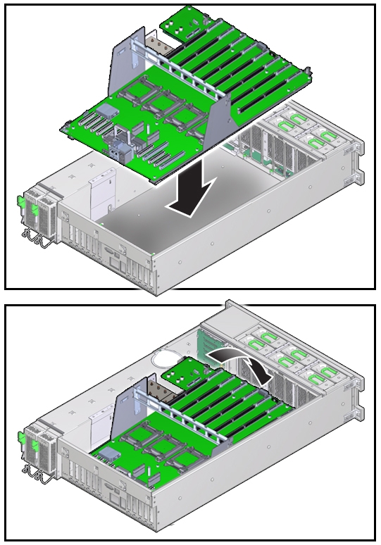
- Ensure that the keyed holes in the plate attached to the underside of the motherboard are aligned with the locking standoffs in the chassis.
-
Slide the motherboard toward the back of the server. Ensure that motherboard rear connectors
fit completely into the holes provided in the chassis sheet metal.
This action locks the motherboard and aligns the captive screw on the motherboard plate (towards the front of the server) with its thread hole in the chassis.
-
To secure the motherboard to the chassis, tighten the captive screw.
- Remove the CPU cover plates from the relevant sockets.
- Reinstall the CPUs and heatsinks.
-
Reinstall the power supply cable to the motherboard.
Connects to the motherboard from the power supply backplane.
- Reinstall the disk backplane power and data cables.
- Reinstall any USB flash drives that were removed from the internal USB ports.
- Reinstall the system battery.
-
Carefully thread the to-PCIe card end of each cable, SAS, NVMe (if present), and, ESM, between
the CPU 0 heatsink and the power supply side wall and in to the PCIe area.
Some of the cable connectors only fit one way between the CPU 0 heat sink and power supply side, as the space is very narrow.
-
Reinstall the air divider.
The divider is mounted to the power supply side wall using two tabs that are inserted into slots in the side wall.
- Position the air divider so that its two tabs align with the two slots in the power supply side wall.
-
Slide the air divider downwards so its tabs fully engage with the slots in the power supply
side wall.
Ensure that the flanges on the divider enter their respective slots on the side wall and that the Fault Remind button extender is aligned with the button on the motherboard.
-
Insert cables (SAS, NVMe, ESM) into the air divider cable shield by gently prying the shield
[A in the illustration below] away from the power supply side wall enough to slide the cables inside
one at a time; starting with SAS, then NVMe (if present), then ESM.
Each cable should be flat against the power supply side wall and not crossing over any other cable. For the proper cable routing order, see the following illustration.

- Attach cables to the three air divider cable clips in the order shown in the illustration above.
- Then, route the cables through the slot in the air divider [B in the illustration above] to the disk backplane area.
- Reinstall the ESM module to its dual lock strip on the chassis.
-
Reconnect the SAS/SATA cables and any NVMe cables (if present) to the disk backplane.
See Replace the NVMe Switch Card Cables (FRU) and Replace the SAS 12 Gb/s Internal HBA SAS Cables (FRU).
- To ensure proper cooling through the disk backplane area, slide excess cable length of the SAS, NVMe (if present) and ESM cables towards the PCIe card area.
-
Reconnect the fan board power and data cables to the motherboard.
Note - If the fan board connectors are not reattached to the motherboard, there will be no front panel lights and the fans will not spin up at power on. - Install all memory risers.
-
For a two-CPU system, install the air baffle.
The air baffle is simply lowered into place on the motherboard utilizing available memory riser slot guides. It does not attach to anything.
-
Install all PCIe cards.
See Install a PCIe Card.
Reconnect internal SAS, NVMe (if present) and ESM cables, and external cables as applicable.
- Install the SP card.
-
Prepare the server for operation.
See Prepare the Server for Operation.
Note - The product serial number used for service entitlement and warranty coverage might need to be reprogrammed by authorized service personnel with the correct product serial number.