Remove a Heatsink and CPU (FRU)
When servicing the components in this section, unplug the AC power cords and use ESD protection.
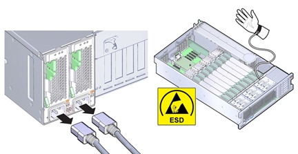
When replacing a failed CPU, use this procedure to remove a heatsink and CPU.
Before You Begin
-
For serviceability considerations, see Component Serviceability.
-
For CPU designation information, see Component Designations.
- Prepare for service.
- Identify the failed CPU.
- Remove the two memory riser cards associated with the failed CPU.
-
Remove the heatsink:
-
Unscrew the four Phillips screws from the heatsink.
Turn the screws alternately one and one half turns until they are fully removed.
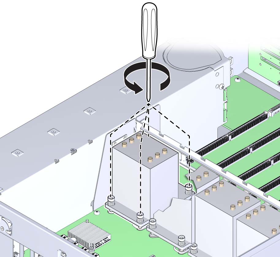
A thermal compound applied to the top of the CPU facilitates heat transfer to the heatsink and acts as an adhesive.
-
To remove the heatsink, break the seal created by the thermal compound by slightly twisting
the heatsink left and right while pulling it upward.
Do not allow the thermal compound to contaminate other components. Retain the heatsink. You need to reuse it.
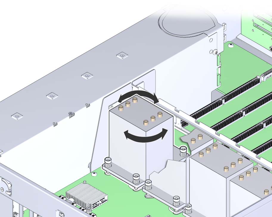
-
Remove the heatsink from the server.
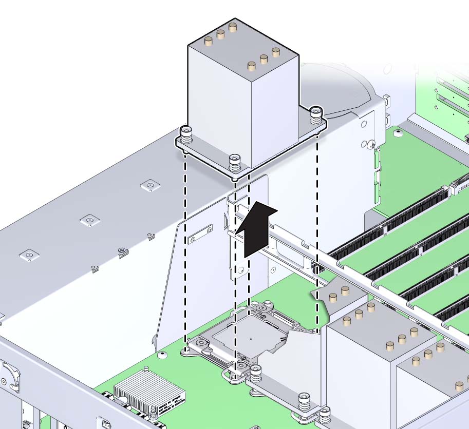
- Place the heatsink upside down on the work space.
-
Use an alcohol pad to clean the thermal compound from both the bottom of the heatsink and the
top of the CPU.

Caution - Component damage. Failure to clean the thermal compound from the heatsink and the CPU prior to removing the CPU could result in accidental contamination of the CPU socket, the removal tool, or other components. Also, be careful not to get the grease on your fingers as this could result in contamination of components.
To access the CPU, the CPU load plate needs to be opened. The load plate is locked in its closed position by the load plate lever.
-
Unscrew the four Phillips screws from the heatsink.
-
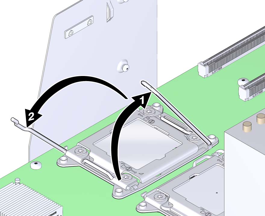
Open the spring-loaded CPU load plate release levers by pushing them down and moving them
slightly toward the CPU socket and away from their retaining clips
The levers are numbered by their required order of operation. The left-side lever (when viewed from the front of the server) must be opened first.
-
Rotate the levers to the fully-open position.
When the second lever is in its fully-open position, the load plate is unlocked.
-
To open the load plate, lift the unhinged end to its fully-open position.

Caution - Component damage. The pins of the CPU socket can be easily damaged. To remove the CPU, use the correct CPU replacement tool.
-
To remove the CPU, use the CPU replacement tool:
The tool is used to remove and install the CPU in the socket. The top side of the replacement tool has a button in the center and a tab on one side. Pressing down on the button opens the tool. Pressing the tab closes the tool (and releases the button).
Note - Ensure that you use the correct CPU replacement tool. The correct tool has part number G29477-002 affixed to the side, and it has a green label. However, the label color alone is not an indicator of the correct tool. Verify that the part number is correct.-
Press down on the release button on top of the replacement tool.
This action opens the tool.
On one corner of the tool there is a label with a downward pointing triangle. Likewise, the CPU is marked with a triangle on one of its corners. This is a key that aligns the tool and the CPU with the CPU socket. The tool and the CPU are correctly positioned with the socket when all of the triangles are aligned.
-
Orient the bottom of the tool over the CPU, ensuring that the triangle on the tool aligns with
the triangle on the CPU.
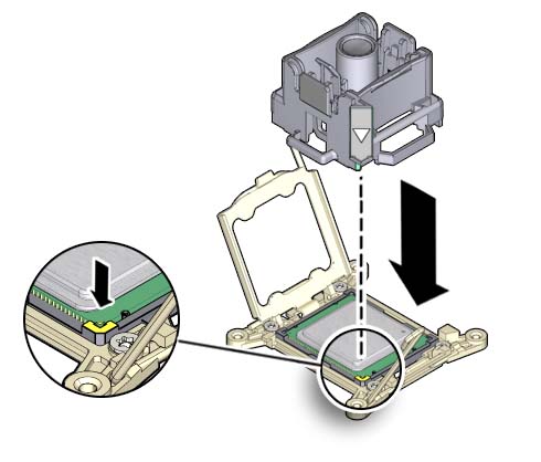
- Lower the tool onto the CPU, ensuring that it sits evenly on the CPU.
-
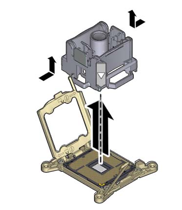
Push the release tab away from the center button.
This action is accompanied by a click sound as the tool closes and grabs the CPU.
-
To remove the CPU, lift the tool upward and out of the server.
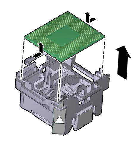
- Turn the tool over, so the metal CPU contacts are facing upward and the topside of the tool is facing downward.
- Hold the CPU by its edges.
-
On the topside of the tool (which is facing downward), pull the release tab away from the
center button.
This action is accompanied by a click sound as the tool releases its hold on the CPU.
-
Remove the CPU from the tool taking care not to touch the metal contacts on the
underside.
-
Press down on the release button on top of the replacement tool.
Next Steps