Input/Output (I/O) Subsystem
The server I/O storage subsystem consists of the following:
Eleven PCIe Gen 3 Slots
The server contains 11 PCIe Gen 3 slots, of which nine are x8 slots and two are x16 slots. All 11 slots are available in a four-CPU configured server. Only the first six slots (1-6) are available in a two-CPU configured server.
Slot 2 is reserved for the HBA that can support up to six SAS/SATA (mechanical or SSD) drives in all six drive slots.
Slot 1 can be used for a factory option PCIe NVMe Switch Card that can support up to four NVMe SSDs in drive slots 2 through 5.
Note - The NVMe Switch card is only supported in PCIe slot 1 and will not work in other PCIe slots.
For slot designation information, see PCIe Slot Designations.
Two Internal and Four External High-Speed USB Ports
The two internal USB ports are located on the motherboard between the disk drive backplane and the PSU backplane boards. These ports can take a standard USB flash device, which can be used for system booting. Your system might be equipped with a preinstalled Oracle System Assistant USB device.
The Oracle System Assistant provides a separately bootable device that aids in the installation of the primary host OS, server hardware configuration, and the firmware upgrade process. Do not use the Oracle System Assistant USB drive as the primary host boot device or as server storage. If installed in your server, the Oracle System Assistant USB drive must be installed in the port labeled "OSA USB."
For port designations, see DVD, Storage Drive, and USB Designations.
Additionally, the server has four external USB ports, two on the front panel and two on the back panel. See External Components and Features.
Four Onboard 10GbE Ports
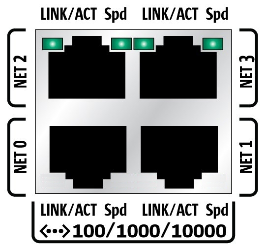
Four 10 GigabitEthernet ports are located on the back panel of the server (see Back Panel Connector Locations). From left to right, the two bottom ports are NET 0 and NET 1; the two top ports are NET2 and NET 3, as shown in the following illustration.

BIOS detects the Ethernet ports in the following order during server boot:
-
NET 0
-
NET 1
-
NET 2
-
NET 3
Note - You can change the boot priority using the Boot Device Priority screen available in the Boot menu of the BIOS Setup Utility.
The device naming for the Ethernet interfaces is reported differently by different interfaces and operating systems. The following illustration explains the logical (operating system) and physical (BIOS) naming conventions used for each interface.
Note - Naming used by the interfaces might vary from that listed below, depending on which devices are installed in the system.
|