Replace the SAS 12 Gb/s Internal HBA SAS Cables (FRU)
When servicing the components in this section, unplug the AC power cords and use ESD protection.
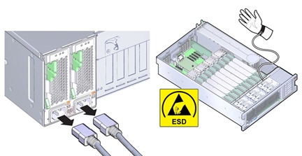
- Prepare the server for service.
-
Remove the P0 MR0/MR1 memory risers.
This gives you room to access the cables for removal. See Remove a Memory Riser Card.
-
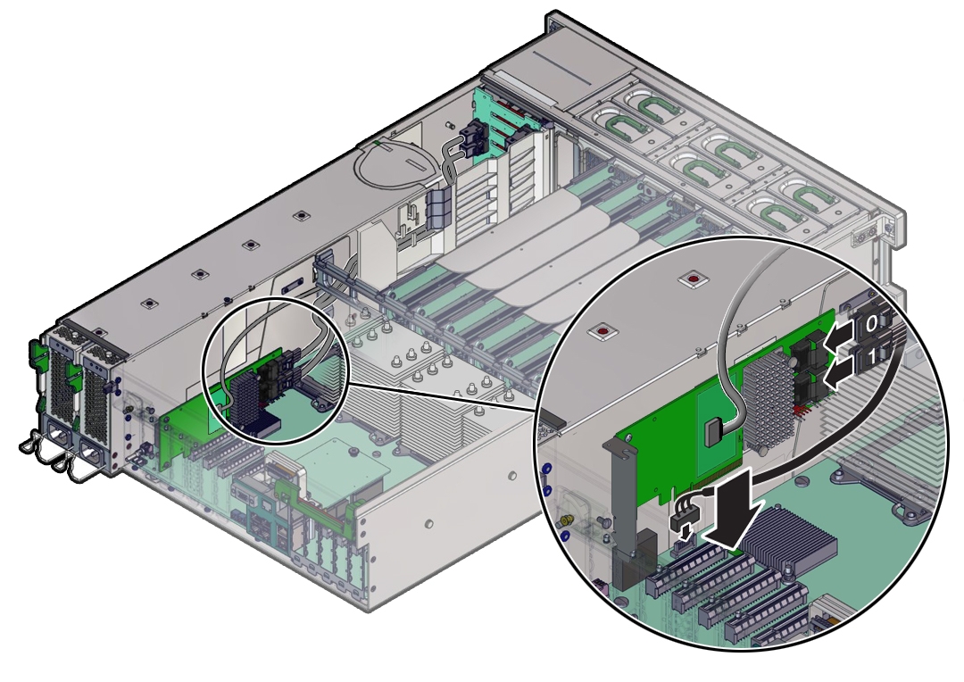
Disconnect the two SAS cables from the HBA card in PCIe slot 2 and the DVD SATA cable (that
branches off of the HBA SAS cables) from the motherboard.
If needed, you can first remove the HBA card from its PCIe slot to gain better access to the cable connectors.
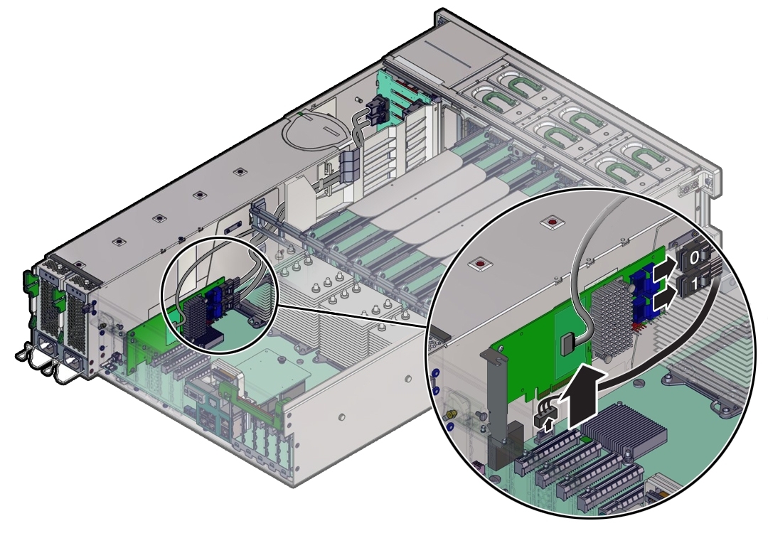
-
Disconnect the two SAS HBA cables (0 and 1) from the disk backplane board.
The white labeled cable is 0, and the yellow labeled cable is 1.
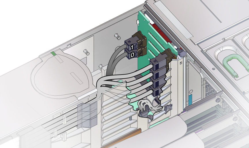
-
Remove the SAS HBA cables from the air divider, as follows.
-
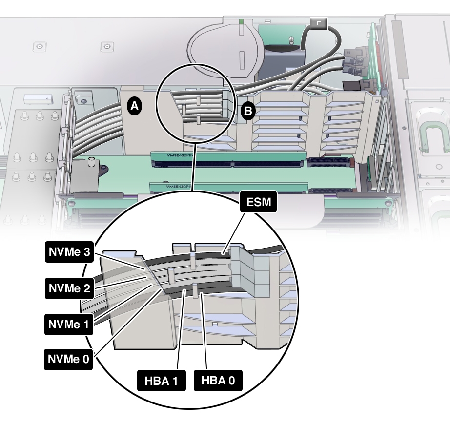
Detach the NVMe (if installed), HBA, and ESM cables from the three cable clips on the memory
riser side of the air divider. Then, carefully lift the cables up and out of the cable slot [B] in
the air divider that provides access to the disk backplane area.
There are three clips. The HBA cables are attached to the bottom clip.
-
Once the HBA cable is clear of the air divider clips, gently pry the air divider cable shield
[A in the figure above] away from the power supply just enough to allow you to slide out the HBA
cables.
The HBA cables need to be completely free of the air divider.
-
Detach the NVMe (if installed), HBA, and ESM cables from the three cable clips on the memory
riser side of the air divider. Then, carefully lift the cables up and out of the cable slot [B] in
the air divider that provides access to the disk backplane area.
-
Carefully thread the ends of HBA cables you detached from the HBA through the narrow space
between the P0 heat sink and the power supply cage and up and out of the system.
The space between the P0 heat sink and the power supply cage is narrow;.the SAS cable connectors will only fit through one way.

Caution - Hardware damage. Try not to allow the SAS and NVMe (if installed) cables to rub against the CPU0 heatsink radiator fins. They are sharp and can damage the cable insulation.
- To install the replacement cable, carefully thread the to-HBA end of the cables through the narrow space between the P0 heat sink and the power supply cage.
-
Reconnect the SAS HBA cables to the HBA card and the SATA cable to the motherboard.
The white labeled cable is 0, and the yellow labeled cable is 1.
If needed, reinstall the HBA card to PCIe slot 2 if you removed it earlier.
-
Reroute the SAS HBA cables through the air divider to the disk backplane area.
Refer to the figure in step 5 for cable routing.
-
Reconnect the SAS HBA cables to their connectors on the disk backplane.
Refer to the figure in step 4 to determine proper connections.
Note - Any excess cable length should be in the PCIe card area to allow better air flow through the disk backplane area. - Reinstall the P0 MR0/MR1 memory risers you removed earlier.
- Prepare the server for operation.