Location of Replaceable Components
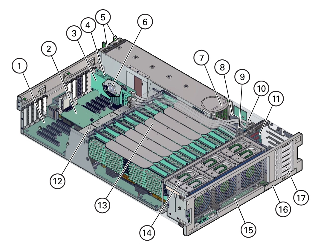
The following illustrations show the Oracle Server X5-4 components:
Replaceable Components

|
|
|
|
|
1
|
Motherboard
|
10
|
HBA SAS cables (2)
|
|
2
|
SP card
|
11
|
Storage drive backplane board
|
|
3
|
HBA card
|
12
|
Heatsinks and CPUs (2 or 4)
|
|
4
|
PCIe NVMe Switch card
|
13
|
Memory riser cards (4 or 8)
|
|
5
|
Power supplies (2)
|
14
|
Fan modules (6)
|
|
6
|
System battery
|
15
|
Fan board
|
|
7
|
Power supply backplane
|
16
|
DVD Drive
|
|
8
|
ESM
|
17
|
Storage drive slots (6)
|
|
9
|
NVMe cables (4)
|
|
|
|
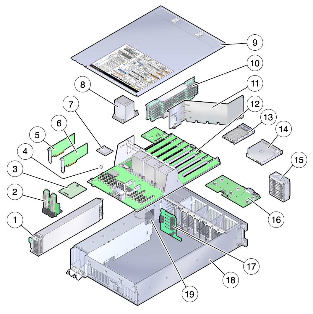
Components (Exploded View)

|
|
|
|
|
1
|
Power supplies
|
11
|
Air baffle (2-CPU configuration only)
|
|
2
|
Power supply backplane board
|
12
|
Motherboard
|
|
3
|
SP card
|
13
|
Storage drive
|
|
4
|
System battery
|
14
|
DVD drive
|
|
5
|
PCIe NVMe Switch card
|
15
|
Fan module
|
|
6
|
HBA card
|
16
|
Fan board
|
|
7
|
CPU
|
17
|
Storage drive backplane board
|
|
8
|
Heatsink
|
18
|
Server chassis
|
|
9
|
Cover
|
19
|
ESM (Energy Storage Module for HBA)
|
|
10
|
Memory riser card
|
|
|
|

