Replace the Disk Drive Backplane (FRU)
This section provides instructions for replacing the disk drive backplane.
When servicing the components in this section, unplug the AC power cords and use ESD protection.
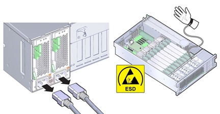
Before You Begin
-
For serviceability considerations, see Component Serviceability.
- Prepare the server for service.
-
Remove and label all disk drives and fillers.
See Remove a Storage Drive (CRU).
To ensure that the drives are returned to their slots, label the drives with their slot position.
- Remove the DVD drive.
-
Disconnect the SAS/SATA cables and any NVMe cables (if present) from the disk
backplane.
See Replace the NVMe Switch Card Cables (FRU) and Replace the SAS 12 Gb/s Internal HBA SAS Cables (FRU).
This will help provide the room needed to remove the disk backplane and its cables.
You do not need to remove the cables from the HBA or NVMe boards.
-
Disconnect the ESM cable from the ESM module.
See Replace the SAS 12 Gb/s Internal HBA ESM Cable (FRU).
Or, simply remove the ESM module from its dual lock strip on the chassis.
-
Move the air divider.
You need to move the air divider so you can access the disk drive backplane board. The divider is mounted to the power supply side wall using two tabs that are inserted into slots in the side wall.
- Lift the air divider so the tabs clear the slots in the power supply side wall.
- Move the air divider away from the side wall and gently rotate the divider and the cables attached to it away from the backplane area and set it on top of installed memory risers.
-
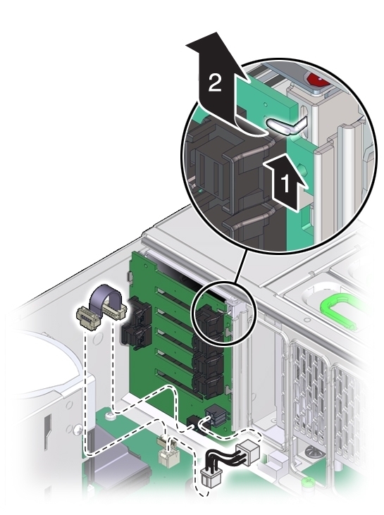
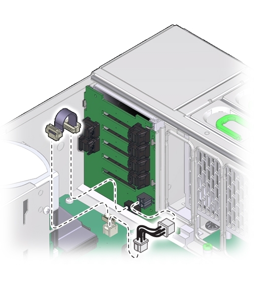
Disconnect the ribbon data cable and the power cable at the bottom of the disk backplane
board.
See the illustration shown in step 8.
-
To release the spring-loaded lever [1], lift it upward [2].
The disk drive backplane sets on metal flanges and is secured by a spring-loaded lever.
-
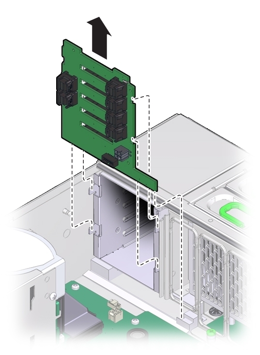
To remove the disk drive backplane, lift it, so it clears the support flanges, and remove it
from the server.
You might need to tilt the board slightly while removing it to slide the DVD connector out from under the disk drive mounting cage.
- Orient the replacement disk drive backplane board in the chassis.
-
Tilt the backplane board and insert its bottom edge in the plastic slot at the bottom of the
server.
The DVD connector on the bottom of the back side of the board needs to be positioned under the disk drive mounting cage.
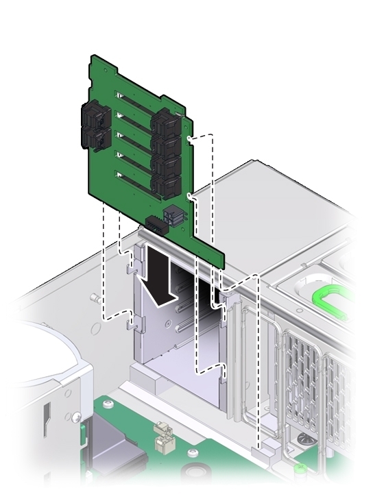
- Lift the spring-loaded metal hook and tilt the backplane board to its upright position.
- Set the board on its support flanges.
- To secure the board, release the metal hook.
-
Reconnect the ribbon data cable and power cable to the bottom of the disk backplane
board.
-
To install the air divider:
Note - The air divider contains the Fault Remind button mechanism. To ensure that the mechanism can engage the motherboard-mounted switch, the divider must be installed correctly.-
Gently rotate the air divider and cables from where you set it down in step 6 back to its
proper position.
Ensure that all cables lay flat against the power supply side wall and do not cross over each other. Do not allow the cables to interfere with the Fault Remind button mechanism (button extension or light pipe).
- Align the two tabs on the divider with the two slots in the power supply side wall.
- Push the tabs into the slots so that the air divider is flush with the power supply side wall.
-
Then, slide the divider downward to lock the tabs in the slots and secure it against the
wall.
To ensure proper alignment of the Fault Remind switch, both tabs must be engaged with their slots.
-
Gently rotate the air divider and cables from where you set it down in step 6 back to its
proper position.
-
Reconnect the SAS and any NVMe cables to the disk backplane.
See Replace the SAS 12 Gb/s Internal HBA SAS Cables (FRU) and Replace the NVMe Switch Card Cables (FRU).
-
Reconnect the ESM cable to the ESM.
See Replace the SAS 12 Gb/s Internal HBA ESM Cable (FRU).
Or, if you removed the ESM, reattach it to the dual lock strip on the chassis.
- Install all disk drives and filler panels.
- Install the DVD drive.
-
Prepare the server for operation.
See Prepare the Server for Operation.
Note - The product serial number used for service entitlement and warranty coverage might need to be reprogrammed by authorized service personnel with the correct product serial number.