PCIe Card and DPCC Overview
This section contains reference information for PCIe cards and DPCCs, including DPCC population rules.
DPCC and PCIe Card Slot Locations and Numbering
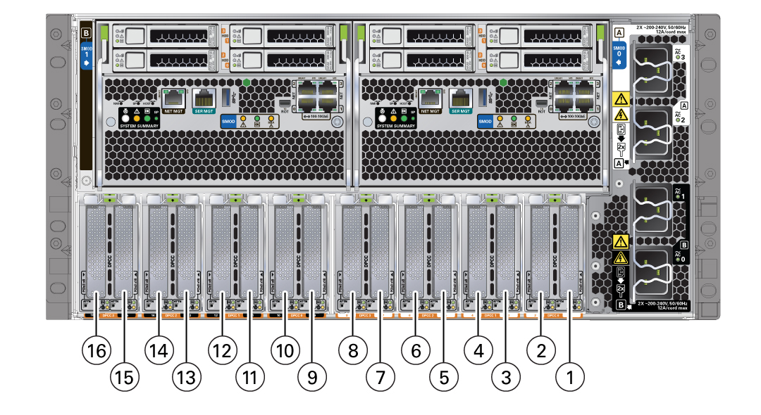
The eight Dual PCIe Card Carrier (DPCC) slots are arranged in a single row at the server back panel. The slots are designated from right to left as DPCC 0–DPCC 7.
Each DPCC occupies two PCIe slots, for a total of sixteen slots. Sixteen PCIe chassis slots support eight PCIe carriers. The PCIe slots are designated from right to left as PCIe 1–PCIe 16.
-
DPCC 0 contains PCIe slots 1 and 2
-
DPCC 1 contains PCIe slots 3 and 4
-
DPCC 2 contains PCIe slots 5 and 6
-
DPCC 3 contains PCIe slots 7 and 8
-
DPCC 4 contains PCIe slots 9 and 10
-
DPCC 5 contains PCIe slots 11 and 12
-
DPCC 6 contains PCIe slots 13 and 14
-
DPCC 7 contains PCIe slots 15 and 16
The following figure shows the PCIe slot numbering.

|
Server PCIe Card Slots
The server chassis contains sixteen PCIe 3.0 slots (eight x8 slots, eight x16 slots) accessible at the back of the server that connect to eight PCIe Gen 3 DPCCs, each containing one or two supported PCIe cards. Each system module (SMOD) controls eight PCIe slots (four x8 slots, four x16 slots).
The server also contains two PCIe Gen 3 slots, which are located internally (and not directly accessible) on SMOD0 and SMOD1. These internal PCIe slots are used for the server HBA components and provide SAS connectivity to the server storage drives.
Dual PCIe Card Carriers (DPCCs)
The server contains eight hot-service PCIe Gen 3 DPCCs. Each DPCC has two low-profile PCIe Gen 3 slots, an 8-lane slot and a 16-lane slot. Each DPCC can contain up to two PCIe cards.
DPCCs connect directly to connectors on the back of the CMODs, so DPCCs and CMODs have a one-to-one relationship with one another. In a four CMOD-configured server, the first four slots (right to left from the back of the server), are active. In an eight CMOD-configured server, all eight slots are active.
DPCC Indicator Panel
Two indicator panels are located on the front of the DPCC, one for each slot. Both panels include an OK indicator, a Fault-Service Required LED, and an ATTN button. The buttons are used to alert the OS to a request for DPCC/PCIe card removal and to request acknowledgement of a DPCC installation. For a DPCC removal, the OS responds by lighting the indicators on the front of the DPCC. For an installation, the OS lights the green OK indicators.
DPCC Population Rules
Follow these DPCC population rules:
-
All eight DPCCs must be installed in the system regardless of the system configuration and whether the DPCC contains a PCIe card.
-
One populated DPCC must be installed for each CMOD (four or eight populated DPCCs).
For component serviceability, locations, and designations, see Replaceable Components.