DIMM Population Rules
The population rules for adding DIMMs to the server are as follows:
-
The server supports 64 GB quad-rank (QR) Load-Reduced DIMMs (LRDIMMs), 32-GB dual-rank (DR), and 16-GB DR Registered DIMMs (RDIMMs).
-
Do not mix 64-GB LRDIMMs and 16-GB or 32-GB RDIMMs in the same server. If the server has 64-GB LRDIMMs installed, you cannot install 16 GB or 32 GB RDIMMs and vice versa.
-
Within a memory channel, DIMMs must be populated in the black sockets first, and then in the white sockets.
-
If you are installing a mix of RDIMM sizes (for example, 16-GB and 32-GB), install the larger size RDIMMs first, then the smaller RDIMMs, until all of the RDIMMs are installed.
-
The server will operate properly with a minimum of one DIMM installed per processor.
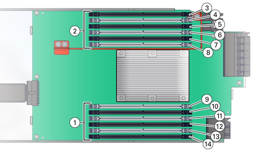
The following illustration shows the location of the memory buffers, the groups of DIMM slots, and the slots assigned to each channel.

|
DIMM Slot Population Order
The DIMM slot population order is as follows:
Note - Always populate the DIMM slot furthest from the memory buffer first.
-
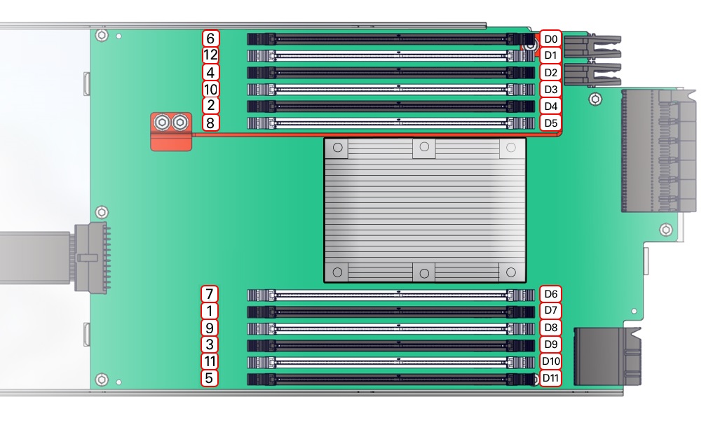
Installation Order DIMM: 1 D7, 2 D4, 3 D9, 4 D2, 5 D11, 6 D0, 7 D6, 8 D5, 9 D8, 10 D3, 11 D10, 12 D1
-
Populate the slots with black slots and black levers: D0 D3 D6 D9 D12 D15 D18 D21
The slot population for the minimum DIMM configuration is D0/D6/D12/D18 per CMOD
-
Populate the white slot, white lever slots: D2 D5 D8 D11 D14 D17 D20 D23
The following table describes the proper order in which to populate DIMMs in a CMOD using the numbered callouts in the above figure, and the DIMM socket labels (D0 through D11).
|
The physical layout of the CMOD memory DIMMs and DIMM installation order is shown in the following figure.

For component serviceability, locations, and designations, see Replaceable Components.
DIMM Rules
The DIMM installation rules aim to maximize the memory bandwidth available by spreading the memory across all six memory channels.
When installing DIMMs, consider the following rules:
-
When two DIMMs are in a channel, the channel speed defaults to the maximum supported speed (listed in the DIMM's SPD and read by BIOS) of the slowest DIMM in the channel. For example: if an 1866 MT/s-compliant DIMM is installed in a channel with a 2133 MT/s -compliant DIMM, the channel speed is limited to 1866 MT/s.
-
A maximum of 8 logical ranks (ranks seen by the host) per channel is allowed.
-
When one DIMM is used, it must be populated in DIMM slot 0 (farthest away from the CPU) of a given channel.
-
When single-rank or dual-rank RDIMMs are populated for 2DPC (two DIMMs per channel), always populate the higher quantity rank DIMM first (starting from the farthest slot). For a 2SPC (two slots per channel) example, first populate a dual-rank DIMM in the DIMM0 slot. Then a single-rank DIMM may be populated in the DIMM1 slot.
-
All CMODs should be populated identically.
-
Memory quantity needs to be equal across all CMODs.
-
All DIMMs in a system should be the same type and size.
-
The minimum DIMM configuration as shipped from the factory is four 16-GB DIMMs in each CMOD, installed is slots D0, D6, D12 and D18.
An upgrade of four DIMMs for each CMOD is allowed in this configuration by installing four DIMMs in slots D3, D9, D15 and D21.
-
Aside from an upgrade to the minimum shipped configuration (stated above), DIMMs must be added to each CMOD in sets of eight (one for each memory buffer channel). Add eight DIMMs to each CMOD starting with CMOD0 and ending with CMOD3 (four-CMOD configuration) or CMOD7 (eight-CMOD configuration). After all CMODs are populated, go back to CMOD0 and repeat the sequence adding the next set of eight DIMMs to each CMOD.
For example: CMOD0 gets the initial eight DIMMs, followed by CMOD1 with the next eight DIMMs, continuing with all CMODs in the configuration. When 32 DIMMs (4-CMOD) or 64 DIMMs (8-CMOD) have been added across all CMODs in the configuration, go back to CMOD0 for the next set of eight DIMMs and continue this population pattern.
-
Each CMOD must only contain one size of DIMM. Mixing of different size memory within a CMOD is not allowed. Size mixing between CMODs is not allowed.
-
Mixing of LVDIMM and LRDIMM in the same chassis is not allowed.