Remove a Power Supply
You might need to remove power supplies to replace a PS or to access the release latch for the front indicator module (FIM).
-
Prepare the server for hot service.
See Preparing the Server for Component Replacement.
Note - This procedure can also be completed as a warm service or cold service procedure. -
Identify the power supply that requires removal.
Access this component directly from the front of the server. View LEDs when the server is in Standby power mode.
The following status indicators (LEDs) are lit when a power supply fault is detected:
-
Front and back Fault-Service Required LEDs
-
Amber Fault-Service Required LED on the faulty power supply
-
Back Power Supply Fault-Service Required LED located on the server front panel FIM
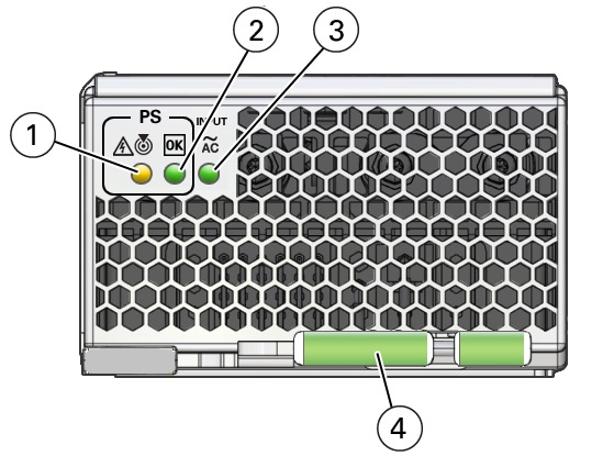
 Call OutStatus LED or ButtonIcon and ColorDescription1Fault-Service RequiredLocate LED
 Amber
Amber WhiteIndicates the location of the power supply in the server:
-
Off – Power supply is operating normally,
-
Fast blink – Use Oracle ILOM to activate this LED to enable you to locate a power supply quickly and easily.
Lights steady on when the power supply is in a fault state.2OKPower Supply OK LED GreenIndicates the functional state of the power supply:
-
Off – PS is disconnected
-
Steady On – PS is powered on and functioning normally. When this LED is lit, the AC OK LED is also lit.
Note - Oracle ILOM signals a fault on any installed power supply that is not connected to an AC power source, since it might indicate a loss of redundancy.
3AC OK LED~ACGreenIndicates the operational state of the power supply:-
Off – PS is not connected to an AC power source.
-
Steady On – PS is connected to a properly rated AC power source.
4Ejector leverNoneUsed to release the power supply from the chassis
Note - To access the FIM release latch, remove the top power supply (PS3). -
-
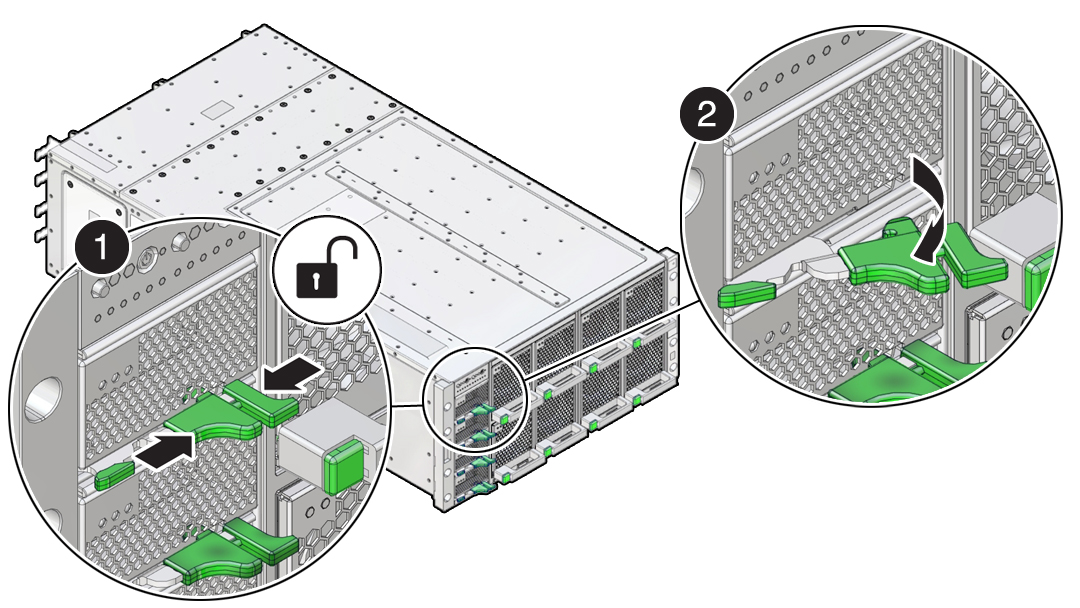
To unlock the power supply lever, squeeze together the two release latches
at the end of the lever (1).
This action is accompanied by a click sound.

-
To disengage the power supply from its internal connector, rotate the
lever to the left (2).

Caution - Pinch point. When operating the lever, keep your fingers clear of the hinged end of the lever.
The pawl at the hinged end of the lever engages the sidewall of the server and provides the pivot point for leverage to disengage the power supply. This action leaves the power supply extending partially from its slot.
-
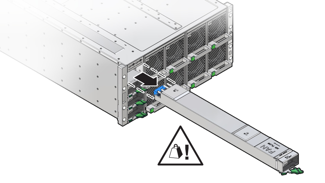
To remove the power supply, use two hands to slowly slide it completely
out of the server.
