|
|
|
|
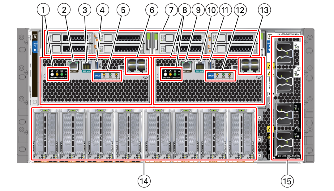
1
|
SMOD1 System B SYSTEM SUMMARY status indicator LEDs:
|
|
|
2
|
SMOD1 System B NET MGT
Oracle ILOM (SP) network management 10/100/1000 GbE Network
Ethernet port.
|
|
|
3
|
SMOD1 System B SER MGT
The SMOD1 System B serial management port service processor
labeled SER MGT port uses an RJ-45 cable and terminal (or
emulator) to provide access to the Oracle ILOM command-line
interface (CLI).
|
|
|
4
|
SMOD1 System B USB
The SMOD1 System B USB 3.0 port supports hot-plugging of
devices.
|
|
|
5
|
SMOD1 System B Status indicators:
|
|
|
6
|
SMOD1 System B NET0-3
Four 10 GbE Network ports labeled NET0, NET1, NET2, and
NET3
|
|
|
7
|
Four server storage drives labeled 0-3 (SAS HDD/SSD)
-
SMOD0 System A: Storage drives 0 through 3: Top row:
3, 1 Bottom row: 2, 0
-
SMOD1 System B: Storage drives 0 through 3: Top row:
3, 1 Bottom row: 2, 0
|
|
|
8
|
SMOD0 System A SYSTEM SUMMARY status indicators:
|
|
|
9
|
SMOD0 System A NET MGT
Oracle ILOM service processor (SP) network management
10/100/1000 GbE Network Ethernet port.
|
|
|
10
|
SMOD0 System A SER MGT
Serial management port labled SER MGT uses an RJ-45 cable and
terminal (or emulator) to provide access to the Oracle ILOM
command-line interface (CLI).
|
|
|
11
|
SMOD0 System A USB
USB 3.0 port supports hot-plugging of devices.
|
|
|
12
|
SMOD0 System A Status indicators
|
|
|
13
|
SMOD0 System A NET0-3
Four 10 GbE Network ports labeled NET0, NET1, NET2, and
NET3.
|
|
|
14
|
PCIe card slots 1 (right) through 16 (left)
PCIe card slots 1 (right) through 16 (left): Dual PCIe card
carriers (DPCC) that contain one or two low-profile PCIe cards.
One DPCC populates two chassis PCIe card slots.
SMOD0 System A: DPCC 0, DPCC 1, DPCC 2, DPCC 3; SMOD1 System
B: DPCC 4, DPCC 5, DPCC 6, DPCC 7
|
|
|
15
|
AC power block
AC inputs with cable clips (AC 0 through AC 3):
SMOD0 System A: AC 3 , AC 2 (Top pair); SMOD1 System B: AC 1,
AC 0 (bottom pair)
|
|
