Controls and Indicators
Use the buttons, switches, and status indicators on the front and back of the server, server management software, and Oracle ILOM to troubleshoot the server:
-
Server Boot Process and Normal Operating State Indicators
-
Locate Button/LED Indicator On
-
Over Temperature Condition
-
PSU Fault
-
Memory Fault
-
CPU Fault
-
Fan Module Fault
-
SP Fault
-
Front Panel Lamp Test
Note - For the error state scenarios described below, the OK indicator state depends on presence of redundant components and the severity of the fault.
Server Boot Process and Normal Operating State Indicators
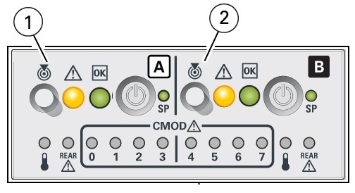
A normal server boot process involves System A (SMOD0) or System B (SMOD1) service processor SP OK indicator and System OK indicator. The following illustration shows SMOD0 System A (callout 1) and SMOD1 System B (callout 2).

|
The following table describes the indicator activity during a normal boot sequence.
|
Locate Button/LED Indicator On
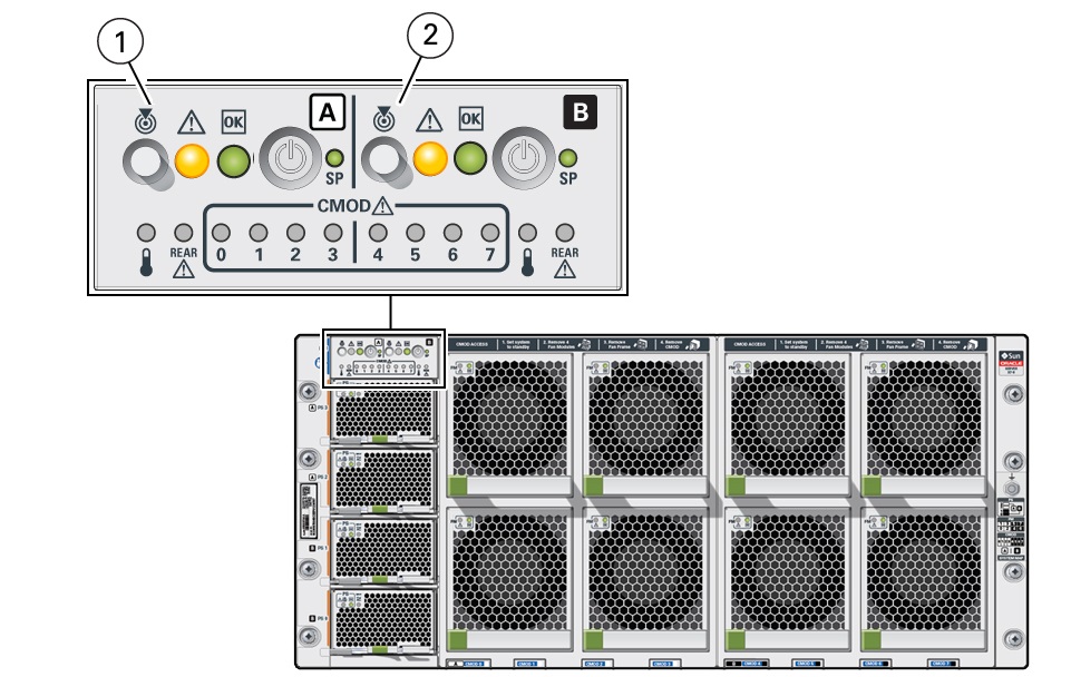
Locate Button/LEDs are white combination button/indicators that are located on both the front FIM and back panel at SMOD0 and SMOD1. To deactivate (or activate) the Locate Button/LED, press and release the Locate button. When the Locate Button/LED is on, the LED blinks at the fast blink rate. You can turn the Locate Button/LED off remotely from Oracle ILOM, or by pressing a Locate button on the chassis. The buttons on the server front and back allow you to manage System A (SMOD0) and System B (SMOD1) Locate Buttons/LED indicators locally.
-
Turn a Locate Button/LED on remotely from Oracle ILOM to locate the server in a rack. Typically, a server readied for service is placed in Standby power mode and the SMOD0 or SMOD1 Locate indicator is lit.
-
Press the SMOD0 or SMOD1 Locate Button/LED button to prove physical presence. Some service procedures require you to prove physical presence by pressing the Locate Button/LED.
The following figure shows two Locate Button/LEDs for System A [callout 1] and System B [callout 2] on the server front panel FIM.

|
Over Temperature Condition
For a server in an over-temperature state, the server amber over-temperature indicator and the amber Fault-Service Required LEDs (front and back) are steady on. The states of the front and back green On Standby, System OK, and the green SP indicators depend on the severity of the condition.
PS Fault
For a server with a power supply (PS) in a fault state, the server amber Fault-Service Required LEDs (front and back) and the amber Fault-Service Required indicator on the PS0-3 are steady on. The front and back green On/Standby, System OK, and the green SP indicators are steady on.
Memory Fault
For a server with a fault in the memory subsystem, the server amber Fault-Service Required LEDs (front and back) and an amber CMOD Fault-Service Required LED are steady on. The front and back green On/Standby, System OK, and the green SP indicators are steady on.
CPU Fault
For a server with a fault in the processor subsystem, the server amber Fault-Service Required LEDs (front and back) and an amber CMOD Fault-Service Required LED are steady on. The activity of front and back green On/Standby, System OK, and the green SP indicators vary depending on whether the server can boot successfully. The server might not be able to boot out of Standby power mode.
Fan Module Fault
For a server with a fan module fault, the server amber Fault-Service Required LEDs (front and back) and an amber Fault-Service Required LED on a fan module are steady on. The front and back green On/Standby, System OK indicator, and the green SP indicators are steady on.
Service Processor Fault
For a server with an SP (service processor) fault, the server amber Fault-Service Required LEDs (front and back) are steady on. The front and back System OK indicators and the SP OK indicator are off.
Front Panel Lamp Test
To perform a lamp test of all front panel indicators, press the Locate Button/LED three times within a five second period. All the front and back indicators light up and remain steady on for 15 seconds (see Unison Steady On).