|
|
|
|
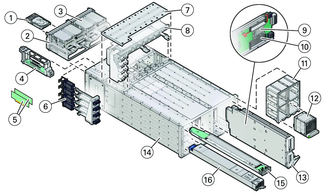
1
|
Storage drives (8), back panel accessible
|
|
|
2
|
System Module 0 (SMOD0), back panel accessible
Includes internal battery, HBA RAID SAS PCIe card, SAS cable,
ESM extension cable, and ESM energy storage module. Not
shown.
|
|
|
3
|
System Module 1 (SMOD1), back panel accessible
Includes internal battery, HBA RAID SAS PCIe card, SAS
cable, ESM extension cable, and ESM energy storage module. Not
shown.
|
|
|
4
|
Dual PCIe carrier card (DPCC) with PCIe cards (8)
|
|
|
5
|
PCIe cards (DPCC slots 4-7 and PCIe slots 9-16 are
nonfunctional in 4-socket systems.)
|
|
|
6
|
AC power block
The AC power block is not a removable component.
|
|
|
7
|
Top access panel
|
|
|
8
|
Midplane assembly
|
|
|
9
|
Processor, front panel accessible
|
|
|
10
|
Memory, front panel accessible
|
|
|
11
|
Fan frame (2), front panel accessible
|
|
|
12
|
Fan module (FM) (8), front panel accessible
|
|
|
13
|
CPU module (CMOD) (4 or 8), front panel accessible
|
|
|
14
|
Server chassis
The server chassis is not a removable component.
|
|
|
15
|
Front indicator module (FIM), front panel accessible
|
|
|
16
|
Power supply (PSU) (4), front panel accessible
|
|

