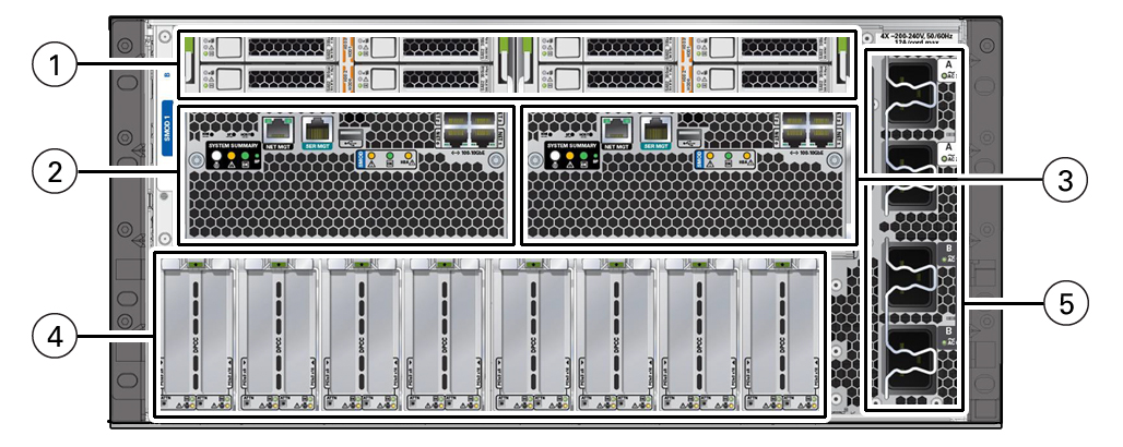
Chassis Back Panel Components
The following illustration shows the chassis back panel.

|
|
|
|
|
1
|
Storage Drives
|
Left facing back of chassis: SMOD1 HDD/SSD slots 0 through
3:
Right facing back of chassis: SMOD0 HDD/SSD slots 0 through
3:
Top row : 3, 1
Bottom row: 2, 0
|
|
|
2
|
System Module A (SMOD0)
|
SMOD0 System A internal components can only be accessed by
removing the SMOD from the server back panel.
|
|
|
3
|
System Module B (SMOD1)
|
SMOD1 System B internal components can only be accessed by
removing the SMOD from the server back panel.
|
|
|
4
|
Dual PCIe card carrier (DPCC) bay
|
The DPCC bay contains eight DPCCs and up to 16 PCIe cards.
|
|
|
5
|
AC power block
|
The AC power block has four AC power inlet connectors, two for
each SMOD. The power block is not a removable component.
|
|
|

