System Socket Mode Configurations
This section provides information about Oracle Server X7-8 single 4-socket systems, dual 4-socket systems, and single 8-socket systems.
Oracle Server X7-8 is divided into two sides, System A and System B, that you can configure into two 4-socket servers, or one 8-socket server. The two sides can operate together as one 8-socket server, or can be configured as independent systems to operate as two 4-socket servers (System A and System B). In both server configurations, Oracle Server X7-8 includes four power supplies PS0-3, eight fan modules (FM0-7), and eight dual PCIe card carriers (DPCCs).
Fan modules and DPCCs receive power from the CPU Modules (CMODs), so in a four-CMOD configuration, only fan modules FM0-3 and DPCCs 0-3 are active. Fan modules FM4-FM7 and DPCCs 4-7 are not powered and are not active. For server component information, see Product Description.
The Oracle Server X7-8 supports four-CMOD and eight-CMOD configurations. Server upgrades from single 4-socket server to dual 4-socket servers require four CPU module upgrade kits with processor modules to upgrade from four CMODS to eight CMODS. Use the additional four CMODs to configure Oracle Server X7-8 with increased processing capabilities. See Oracle X7-8 CPU Packages.
Customers can configure single 8-socket (1x8) servers for dual 4-socket (2x4) mode or dual 4-socket (2x4) servers for single 8-socket (1x8) mode, as required. Service engineers can configure single 4-socket (1x4) servers for dual 4-socket (2x4) mode or single 8-socket (1x8) mode operation, as required. The configuration changes are categorized as customer-replaceable units (CRU) or field-replaceable units (FRU) as follows:
-
Configure a single 4-socket server to a dual 4-socket server (FRU)
-
Configure a dual 4-socket server to a single 8-socket server (CRU)
-
Configure a single 8-socket server to a dual 4-socket server (CRU)
-
Configure a single 4-socket server to a single 8-socket server (FRU)
Note - During Oracle Server X7-8 reconfiguration, administrators must manually clear all existing faults before a 4-socket mode to 8-socket mode change.
Oracle Server X7-8 systems that were ordered as single 4-socket (1x4) servers can be upgraded to dual 4-socket (2x4) or single 8-socket (1x8) servers by service engineers. Since identity information for B-side is preprogrammed as Midplane FRUPROM#1 and SMOD1, when the System B side is booted for the first time after the hardware upgrade (adding CMOD4-7), Oracle ILOM will automatically program the top-level indicator (TLI) information to CMOD4 (Backup Container 2). No manual intervention is required.
The single 4-socket Oracle Server X7-8 system is factory-configured as (2x4) mode, with all System B components installed, except for the CMODs, which service engineers need to install in the empty CMOD bays 4-7. The System B System Module (SMOD1), power supplies, fans, dual PCIe card carriers, and midplane are all pre-tested in the factory when Oracle Server X7-8 system is shipped. Storage drives are included.
For information about server modes, refer to Server Components in Oracle Server X7-8 Installation Guide.
Single 4-Socket (1x4) Server
For the single 4-socket (1x4) server configuration:
-
System Module (SMOD) SMOD0 System A and SMOD1 System B must be installed, but only SMOD0 is active.
-
CPU modules (CMODs) must be installed in slots 0-3. CMOD slots 4-7 are empty.
-
All eight dual PCIe card carrier (DPCC) slots must be installed but only DPCC slots 1, 2, 3 and 4 are active.
PCIe slots 5, 6, 7, and 8 are nonfunctional in 4-socket systems.
-
All eight fan modules (FMs) must be installed but only FMs 0-3 are active.
-
Both fan frames must be installed.
-
PS2 and PS3 are installed and active. PS0 and PS1 are also installed, but inactive. PS2 and PS3 power System A. PS0 and PS1 power System B.
All four AC power connectors on the back panel must be attached with grounded AC power cords.
-
Storage drive bays in System B may have filler panels installed.
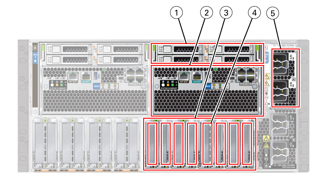
The following illustration shows an Oracle Server X7-8 back panel with a single 4-socket (1x4) server four-CMOD configuration.
|
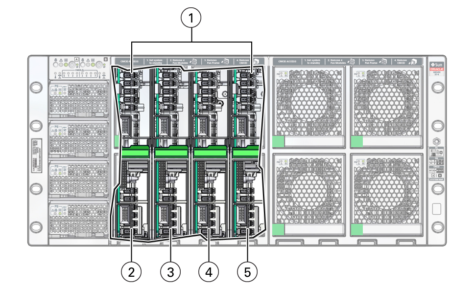
The following illustration shows an Oracle Server X7-8 front panel with a single 4-socket (1x4) server four-CMOD configuration. In the four-CMOD configuration, the first four slots on the left (slots 0-3) are occupied and the four slots on the right (4-7) are unoccupied. In the illustration, the front panel left-side fan modules and fan frame have been removed to show the four active CMODs behind the fan frame. Call out 1 identifies the group of four active CMODs.
|
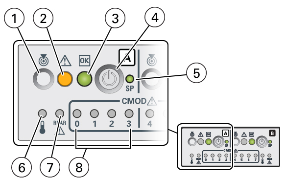
For servers with a single 4-socket (1x4) server configuration, the FIM provides controls and indicators for System A (SMOD0) only. The following illustration shows an Oracle Server X7-8 front panel FIM with a single 4-socket (1x4) server configuration.
|
Dual 4-Socket (2x4) Servers
For the dual 4-socket server configuration:
-
System Module 0 (SMOD0) System A and SMOD1 System B must be installed.
-
CPU Modules (CMODs) must be installed in slots 0-7.
-
Dual PCIe card carrier (DPCC) slots 0-3 and DPCC slots 4-7 must be installed and are active.
-
All eight fan modules (FMs) must be installed. All FMs must be active in the dual 4-socket configuration.
-
Both fan frames must be installed.
-
PS2 and PS3 are installed and active. PS0 and PS1 are also installed and active. PS2 and PS3 power System A. PS0 and PS1 power System B.
-
All four AC power connectors on the back panel must be attached with grounded AC power cords.
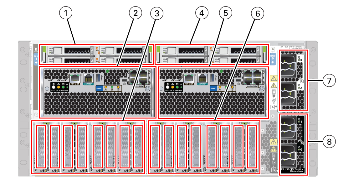
The following illustration shows an Oracle Server X7-8 back panel with a dual 4-socket configuration.
|
The following illustration shows an Oracle Server X7-8 front panel with a dual 4-socket configuration.
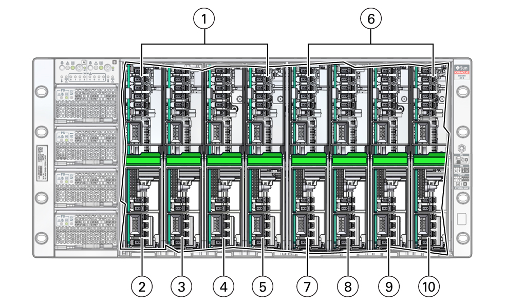
|
For servers with a dual 4-socket configuration, the FIM provides separate controls and indicators for System A (SMOD0) and System B (SMOD1).
The following illustration shows an Oracle Server X7-8 front panel FIM with a dual 4-socket configuration.
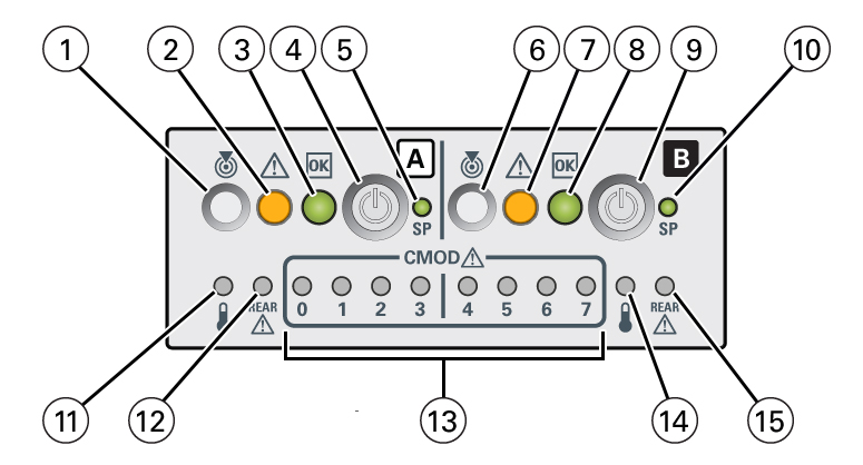
|
Single 8-Socket (1x8) Server
For the single 8-socket (1x8) server configuration:
-
System Module 0 (SMOD0) System A and SMOD1 System B must be installed.
-
Eight CPU Modules (CMODs) must be installed in slots 0-7.
In an 8-socket configuration, System A must have Intel Xeon 81xx series processors installed, and System A and System B processor SKUs and memory (capacity and number of DIMMs per CMOD) must be identical.
-
All eight dual PCIe card carrier (DPCC) slots 0-7 must be installed and must be active.
-
All eight fan modules (FMs) must be installed and all FMs must be active.
-
Both fan frames must be installed.
-
PS2 and PS3 power System A. PS0 and PS1 power System B.
-
All four AC power connectors on the back panel must be attached with grounded AC power cords.
The following illustration shows a server back panel with an single 8-socket (1x8) server configuration.
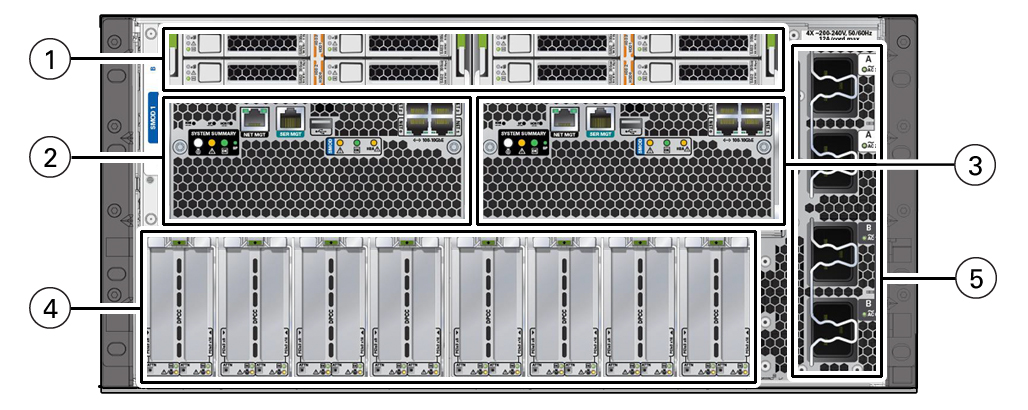
|
The following illustration shows a server front panel with an eight (full) CMOD configuration. Call out 1 identifies the group of four CMODs installed on the left side of the server, and call out 2 identifies the second group of four CMODs installed on the right side of the server.

|
For servers with a single 8-socket (1x8) server configuration, the FIM provides controls and indicators for System A (SMOD0) and System B CMODs 4-7. Other System B (SMOD1) buttons and indicators are not operational. The following illustration shows an Oracle Server X7-8 front panel FIM with a single 8-socket (1x8) server configuration.
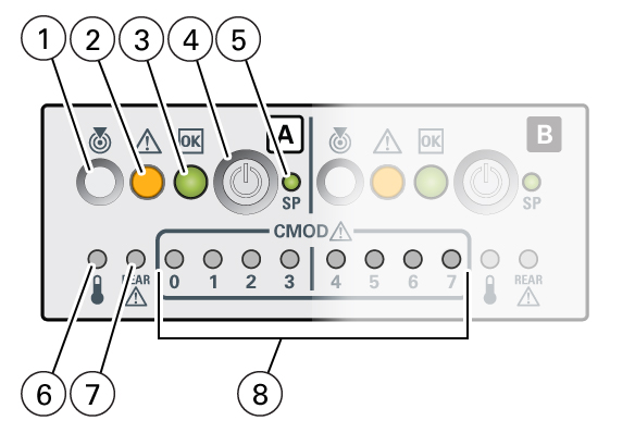
|