Prepare the Server for Cold Service
Note - This procedure uses a combination of the Oracle ILOM web and CLI interfaces. However, the procedure can also be performed using only the Oracle ILOM CLI interface. For more information about the Oracle ILOM CLI interface, refer to the Oracle ILOM documentation.
A cold-service component must be serviced when the server is completely powered off. For more information about component serviceability, see Component Serviceability.
This procedure describes how to prepare the server for service, so you can:
-
Remove, replace, or install cold-serviceable components
-
Remove, replace, or install internal components
-
Use the motherboard processor and DIMM fault remind circuitry
Before You Begin
-
Important: Review the server Product Notes document before performing removal and installation procedures.
-
For troubleshooting information, see Troubleshooting Server Hardware Faults.
-
To power down the server and activate the front panel Locator indicator, do the
following:
-
Log in to the Oracle ILOM web interface.
Type the server SP IP address into a web browser and log in as a user with root or administrator privileges. For more information, see Oracle X4 Series Servers Administration Guide .
-
In the Actions section of the Summary screen, click the Power State Turn Off button.
This action powers off the server to standby power mode. For more power off options, see Powering Off the server.
-
In the Actions section of the Summary screen, click the Locator Indicator Turn On
button.
This action activates the Locator indicator on the server front panel. For more Locator indicator management options, see Managing the Locator Indicator.
-
Log in to the Oracle ILOM web interface.
-
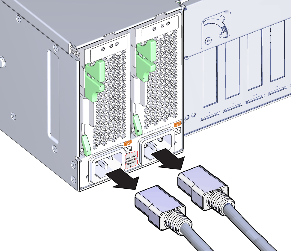
Remove both server power cords.

Caution - Data loss. Removing the power cord when the server is in full power mode results in an immediate shut down of the server. Do not remove the power cord if the server is in full power mode.

-
To slide the server out of the rack to the maintenance position, do the following:
Most component service procedures can be performed without removing the server entirely from the rack. Instead, the server can be slid out of the rack on its support rails to an extended and locked position called the maintenance position.
-
At the back of the server, verify that the cables have sufficient length and clearance to
accommodate the distance required to extend the server to the maintenance position.
The cable management arm (CMA) that is supplied with the server is hinged to facilitate extending the server to the maintenance position. However, ensure that the cables do not impede with, or are damaged by, the sliding movement. If necessary, label and remove cables from the back of the server.
- (Optional) To move the CMA for access to the back of the server, see Release the CMA.
-
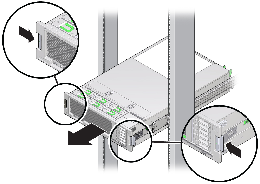
At the front of the server, release the slide rails by pushing the two green latches inward.

-
Slowly pull the server forward until both slide rails lock at the fully extended maintenance
position.
The locking action is accompanied by an audible click. The server is now in the maintenance position and ready for service.
-
At the back of the server, verify that the cables have sufficient length and clearance to
accommodate the distance required to extend the server to the maintenance position.
- (Optional) To remove the server entirely from the rack, see (Optional) Remove the Server from the Rack.
-
Set up an ESD-safe service location.
Set up a space where you can set components. The space needs to be ESD safe. See Performing Electrostatic Discharge and Static Prevention Measures.
-
Remove the top cover. See
Remove the Server
Cover.

Caution - Component ESD damage. Circuit boards and hard drives contain electronic components that are extremely sensitive to static electricity. Do not touch or handle components unless you are wearing a properly grounded anti-static wrist strap.
Next Steps