Component Designations
This section shows the slot naming designations for internal and external
slots:
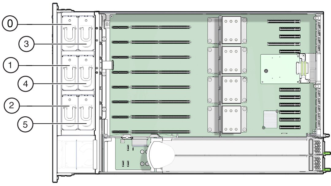
Fan Module Slot Designations
The six fan module slots are at the front of the server and are set in two
rows of three slots. The slots are designated from left to right. As pictured in
the illustration below, the three front row slots are designated as: FM0, FM1,
and FM2. The three back row slots are: FM3, FM4, and FM5.
|
|
|
|
|
0
|
Fan Module, FM 0
|
3
|
Fan Module, FM 3
|
|
1
|
Fan Module, FM 1
|
4
|
Fan Module, FM 4
|
|
2
|
Fan Module, FM 2
|
5
|
Fan Module, FM 5
|
|
CPUs and Memory Riser Card Slots Designations
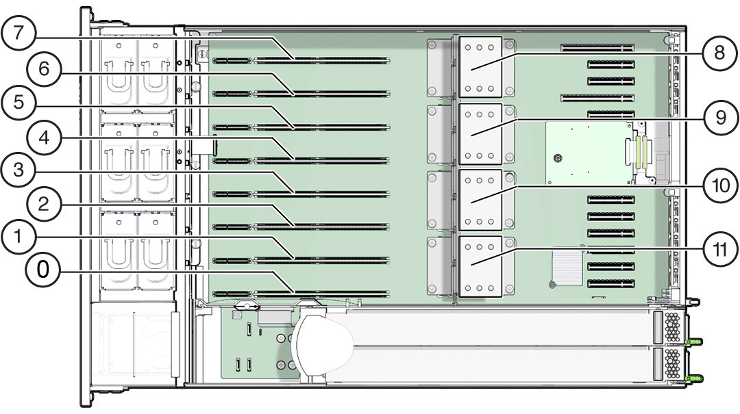
The four CPU sockets are located in the middle of the server and are
designated consecutively from right to left (from the front of the server). The
rightmost socket is CPU-0 and is designated as P0, and the leftmost socket is
CPU-3, designated as P3.
The eight memory riser (MR) card slots are located between the fan module
slots and the CPU sockets. Consecutively from right to left, the rightmost slot
is slot 0, and the leftmost slot is slot 7.
The slots are also designated by their association with the four CPU sockets
(P0-P3). Two slots are assigned to each CPU socket. For example, slots 0 and 1
are paired with CPU socket, P0, and are designated as P0/MR0 and P0/MR1. Slots 2
and 3 are paired with CPU socket, P1 and are designated as P1/MR0 and P1/MR1.
This numbering pattern continues for the remaining slots.
|
|
|
|
|
0
|
MR card slot 0, P0/MR0
|
6
|
MR card slot 6, P3/MR0
|
|
1
|
MR card slot 1, P0/MR1
|
7
|
MR card slot 7, P3/MR1
|
|
2
|
MR card slot 2, P1/MR0
|
8
|
CPU-3 (P3)
|
|
3
|
MR card slot 3, P1/MR1
|
9
|
CPU-2 (P2)
|
|
4
|
MR card slot 4, P2/MR0
|
10
|
CPU-1 (P1)
|
|
5
|
MR card slot 5, P2/MR1
|
11
|
CPU-0 (P0)
|
|
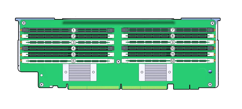
DIMM Slot Designations
The DIMM slots are located on the memory riser cards. The DIMMs are arranged
in two banks of six slots for a total of 12 slots. The slots are designated
numerically from top to bottom. The left bank of slots are designated as
D0–D6. The right bank of slots are designated as D7–D11.
|
|
|
|
|
1
|
Slot D0
|
7
|
Slot D6
|
|
2
|
Slot D1
|
8
|
Slot D7
|
|
3
|
Slot D2
|
9
|
Slot D8
|
|
4
|
Slot D3
|
10
|
Slot D9
|
|
5
|
Slot D4
|
11
|
Slot D10
|
|
6
|
Slot D5
|
12
|
Slot D11
|
|
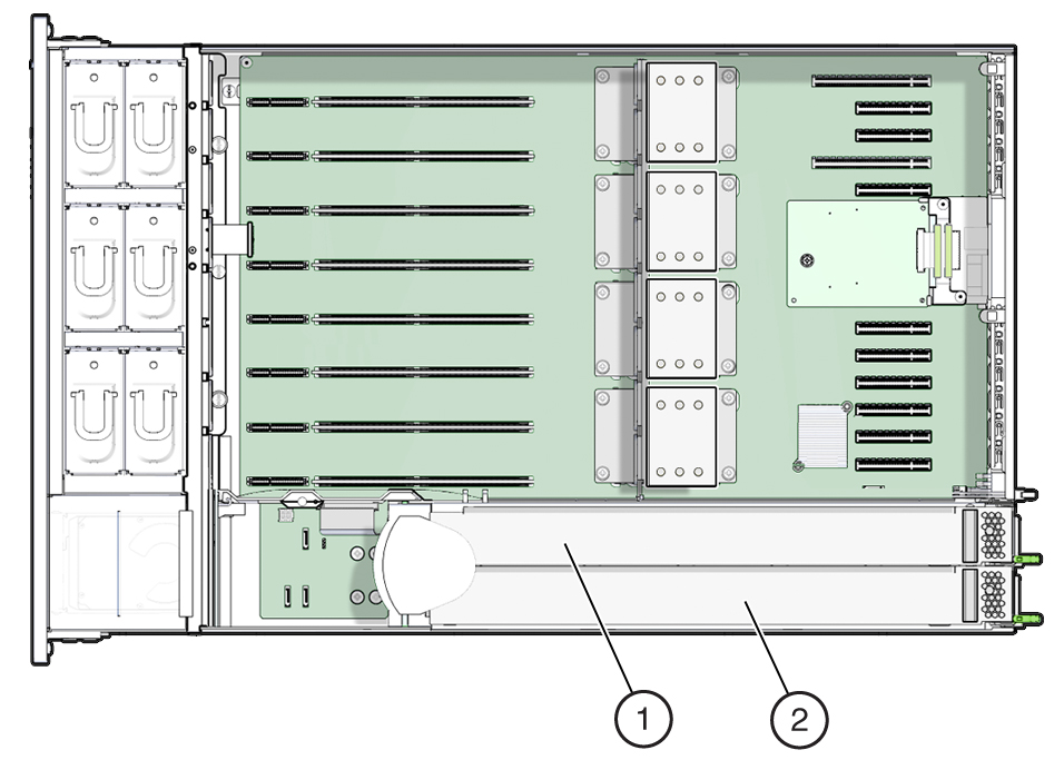
Power Supply Designations
The two power supply slots are located on the right side of the server (from
the front of the server) and are designated from right to left. The slots are
accessible from the back of the server. From the back of the server, the left
slot is designated as PS-0, and the right slot is PS-1.
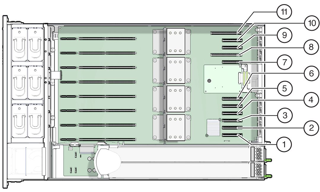
PCIe Slot Designations
The eleven PCIe slots are located inside the server at the back. As viewed
from the front of the server, the slots are divided into two groups, a group of
six on the right of the SP card and a group of five on the left of the SP card.
The slots are designated from right to left. The six slots on the right side are
designated as PCI-1 to PCI-6. The five slots on the left are designated as PCI-7
to PCI-11.
|
|
|
|
|
1
|
PCIe 1
|
7
|
PCIe 7
|
|
2
|
PCIe 2
|
8
|
PCIe 8
|
|
3
|
PCIe 3
|
9
|
PCIe 9
|
|
4
|
PCIe 4
|
10
|
PCIe 10
|
|
5
|
PCIe 5
|
11
|
PCIe 11
|
|
6
|
PCIe 6
|
|
|
|
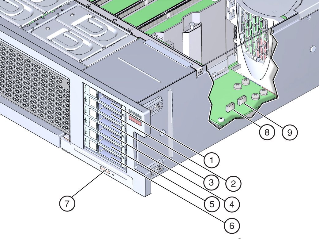
DVD, Storage Drive, and USB Designations
The DVD drive is located at the right lower front side of the front of the
server.
The six storage drive slots are on the right side of the server and are
designated consecutively from bottom to top. The bottommost slot is designated
as HDD-0, and the topmost slot is HDD-5.
The two internal USB slots are located between the disk backplane board and
the power supply backplane board. The front slot is used for the optional Oracle
System Assistant USB stick and is marked "OSA USB".
|
|
|
|
|
1
|
HDD5
|
6
|
HDD0
|
|
2
|
HDD4
|
7
|
DVD
|
|
3
|
HDD3
|
8
|
OSA USB port
|
|
4
|
HDD2
|
9
|
USB port
|
|
5
|
HDD1
|
|
|
|


