Replace the Motherboard (FRU)
When servicing the components in this section, unplug the AC power cords and use ESD protection.
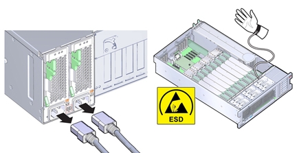
To replace the motherboard, remove and retain internal motherboard-mounted components.
Before You Begin
-
For serviceability considerations, see Component Serviceability.
-
To complete this procedure, you need:
-
Alcohol wipes
-
Thermal compound
-
- Prepare the server for service. See Prepare the Server for Cold Service.
- Remove the SP card. See Remove the SP Card (FRU).
-
Remove all PCIe cards from the server taking care to note their slot assignments. See
Remove a PCIe Card.
The slot population on the replacement motherboard needs to match the population on the failed board.
-
If the server has two CPUs, carefully remove the air baffle, taking care not to damage the fan
board ribbon cable.
Lift the baffle slowly and maneuver its front edge away from the ribbon cable while removing.

Caution - Component damage. Lifting the baffle straight up from the server can damage the fan board ribbon cable. The front support foot for the air baffle is located under the cable.
- Remove all memory riser cards. See Remove a Memory Riser Card.
- Disconnect the fan board ribbon cable from the motherboard.
- Remove the CPUs and heatsinks from the motherboard. See Remove a Heatsink and CPU (FRU)
-
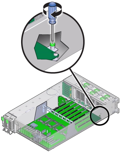
Loosen the green captive screw that secures the motherboard to the chassis.
The screw is located at the left front corner of the motherboard behind FM3.
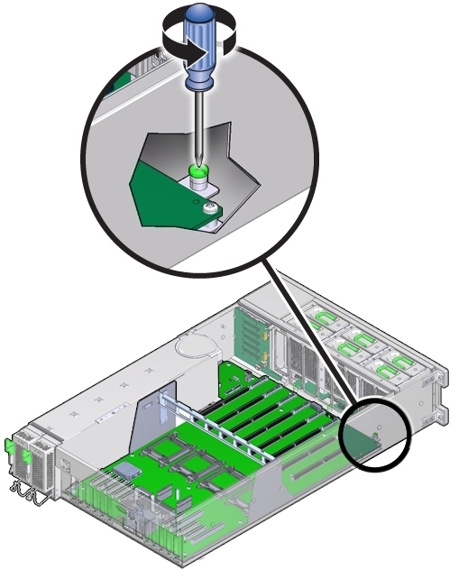
- Disconnect all cables that connect the power supply backplane, disk drive backplane, and fan board to the motherboard.
- Remove the air divider by lifting it out of the chassis.
-
Remove the four bus bar screws securing the motherboard to the power supply backplane.
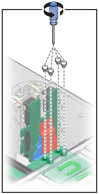
-
Position the cables off to the side, using the tab on the power supply cover.
The motherboard is mounted to a metal plate. The plate has eight keyed slots that align with eight standoffs mounted to the bottom of the chassis. The standoffs lock the motherboard and plate assembly to the chassis. To unlock the assembly, you need to slide the assembly toward the front of the server before you can lift it out.
-
To unlock the motherboard, use the memory riser card guide and the handle above the SP card
slot to slide the motherboard toward the front of the server.
This action unlocks the motherboard and plate assembly.
-
Lift the front end of the motherboard while gently sliding it away from the back of the
server, ensuring that the Locator indicator light pipe extension piece slides out of its hole in the
chassis back wall .
Note - If Locator indicator light pipe extension detaches during removal, ensure that you retrieve it from the server. The extension is a clear plastic piece that transmits light and allows you to activate the Locator indicator switch from the back of the server.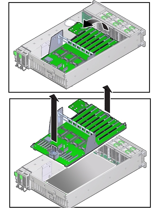
- To remove the motherboard, slowly guide it up and out of the server.
-
Lift the replacement motherboard by the memory riser card guide and the handle above the SP
card slot.
Note - Ensure that the removable light pipe extension piece for the Locator indicator is attached to the indicator switch. The extension is a clear plastic piece that transmits light and allows you to activate the Locator switch from the back of the server.Position the motherboard so that PCIe slots at the back of the server and the memory riser card slots are toward the front.
- Align the motherboard over the server with the memory riser card slots toward the front.
-
Lower the motherboard into the server and guide the light pipe extension piece for the Locator
indicator at the back of the motherboard into its hole on the server back wall.
Ensure that the switch operates easily and is not stuck in the depressed position.
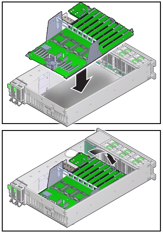
- Ensure that the keyed holes in the plate attached to the underside of the motherboard are aligned with the locking standoffs in the chassis.
-
Slide the motherboard toward the back of the server.
This action locks the motherboard and aligns the captive screw on the motherboard plate with its thread hole in the chassis.
-
To secure the motherboard to the chassis, tighten the captive screw.
- Before install the CPUs, remove the CPU cover plates relevant sockets. See Remove a CPU Cover Plate (FRU).
- Install the CPUs and heatsinks. See Install a Heatsink and CPU (FRU).
- Insert and tighten the four bus bar screws that secure the motherboard to the power supply backplane.
- Install the air divider by aligning it with its guide and lowering it into the server. Ensure that the flanges on the divider enter their respective slots on the side wall and that the plunger for the Fault Remind button is aligned with the button on the motherboard.
- Connect all cables from the power supply backplane, disk drive backplane, and fan board to the motherboard.
- Install all memory risers.
- For a two-CPU system, install the air baffle, ensuring that the foot on the front of the baffle is under the fan board ribbon cable.
-
Install all PCIe cards.
See Install a PCIe Card.
- Install the SP card. See Install the SP Card (FRU).
-
Install the power supply backplane cover plate.
Note - Do not route the cables on the power supply backplane cover plate. -
Prepare the server for operation. See
Prepare the Server for
Operation.
Note - The product serial number used for service entitlement and warranty coverage might need to be reprogrammed by authorized service personnel with the correct product serial number.