Complete the Cluster Page
 | Caution - Take extreme care when specifying the DATA and RECO disk group names. The names must be unique for the cluster you are defining. Check existing grid disks on the storage cells and ensure that they are not already in use. If an existing grid disk is specified for a new cluster, the griddisk is dropped and recreated by older versions of Java OneCommand (prior to patch 19766190), possibly resulting in loss of production data. |
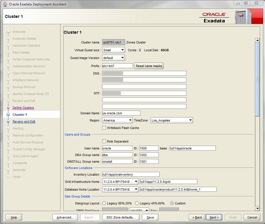
The left pane displays a cluster configuration page for each new cluster that you are creating.
-
Review the cluster configuration page for the first new cluster that you are
creating.

-
Under Software Locations, define the database versions for these items:
-
Grid Infrastructure Home
-
Database Home Location
-
-
Under Disk Group Details, provide this information:
-
In the Diskgroup Layout, chose one of these options:
-
Legacy 80%:20% – Assigns the following sizes to the disk groups:
-
DBFS Diskgroup: Default size (the default size for the DBFS disk group in this selection is the size of the operating system disk slice on disks 0 and 1, which is usually between 29 GB and 31 GB)
-
DATA Diskgroup: 80% size
-
RECO Diskgroup: 20% size
Caution - Choose Legacy only if you have dedicated storage cells per cluster and no storage cell sharing.
-
-
Legacy 40%:60% – Assigns the following sizes to the disk groups:
-
DBFS Diskgroup: Default size (the default size for the DBFS disk group in this selection is the size of the OS disk slice on disks 0 and 1, which is usually between 29 GB and 31 GB.)
-
DATA Diskgroup: 40% size
-
RECO Diskgroup: 60% size
Caution - Choose Legacy only if you have dedicated storage cells per cluster and no storage cell sharing.
-
-
Custom – Allows you to assign your own sizes to the disk groups
-
-
Specify a unique name for the disk groups for this cluster. For this example, these names are specified.
Note - Diskgroup names have a maximum of eight characters.-
DBFS Diskgroup: DBFS_DG
-
DATA Diskgroup: DATAC1
-
RECO Diskgroup: RECOC1
-
-
Select the level of redundancy for the disk groups (DBFS, DATA, and RECO):
-
UNUSED (DBFS disk group only)
-
NORMAL
-
HIGH
-
-
Configure the size of the disk groups (DBFS, DATA, and RECO) for this cluster.
Note - If you are sharing storage servers across clusters, follow the instructions in Verify Storage Server Disk Space to determine the amount of free space that you have in the storage servers for each disk group. In this case, use a custom sizing for the disk groups. -
- Make cluster-specific changes to the Database Name field, if necessary.
-
Verify that the host name (name mask), SCAN name and VLAN information is
correct in the networks area at the bottom of the page (Admin Network, Client
Network and Private Network).
- In the assistant window for your SuperCluster, select Zones in the navigation panel, then click View in the Details column for each of the database zones that are part of this cluster.
-
Note the following entries for each database zone in the Zone Details
screens through the assistant:
-
Management Hostname
-
10Gb Client Hostname 1
-
Exadata IB Hostname
-
VIP Hostname
-
Hostname and VLAN tag for SCAN Address Group
-
-
Locate the following entries in the networks area at the bottom of the
Cluster 1 page in OEDA:
-
Admin Network:
-
Name mask
-
-
Client Network:
-
Name mask
-
VIP Name mask
-
SCAN Name
-
VLAN ID
-
-
Private Network:
-
Name mask
-
-
-
Compare the entries between the Zone Details screens in the assistant
and the Cluster 1 page in OEDA.
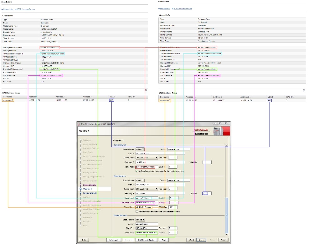
This figure shows how the entries from the two database zones in the Zone Details screens in the SuperCluster Virtual Assistant map to the entries in the networks area at the bottom of the Cluster 1 page in OEDA.

-
Make the appropriate edits in the Cluster 1 page in OEDA to match the
entries from the Zone Details pages in the assistant for each database
zone that is part of this cluster.
Note the following:
-
Certain entries in the Cluster 1 page in OEDA have a single field that would be populated using multiple entries from the individual Zone Details screens in the assistant. For example, there is a single Admin Network: Name mask field in OEDA that is populated using the Management Hostname entries from the Zone Details screens in the assistant for each database zone that is part of the cluster, such as etc14m7iozadm010101 for the first database zone and etc14m7iozadm020101 for the second database zone in the assistant. OEDA will use the percentage sign (%) as a wildcard in these cases (in this example, using etc14m7iozadm0%0101 in the Admin Network Name mask field in OEDA).
-
The following suffixes should be appended at the end of the following entries in the Cluster 1 page in OEDA, even if these suffixes don't appear in the Zone Details pages in the assistant:
-
-client at the end of the entry used in the Client Network: Name mask field.
-
-vip at the end of the entry used in the Client Network: VIP Name mask field.
-
This table shows example entries that might be found in the individual Zone Details pages in the assistant for each database zone and the entries that should be used in the Cluster 1 page in OEDA.
Example Entry in the Assistant for Database Zone 1Example Entry in the Assistant for Database Zone 2Example Entry in Cluster 1 page in OEDAManagement Hostname:etc14m7iozadm010101Management Hostname:etc14m7iozadm020101Admin Network: Name mask:etc14m7iozadm0%010110Gb Client Hostname 1:etc14m7iozadm010101-client10Gb Client Hostname 1:etc14m7iozadm020101-clientClient Network: Name mask:etc14m7iozadm0%0101-clientExadata IB Hostname:etc14m7iozadm010101Exadata IB Hostname:etc14m7iozadm020101Private Network: Name mask:etc14m7iozadm0%0101-priv1VIP Hostname:etc14m7iozadm010101-vipVIP Hostname:etc14m7iozadm020101-vipClient Network: VIP Name mask:etc14m7iozadm0%0101-vipSCAN Address Group: Hostname:zone-scan-3SCAN Address Group: Hostname:zone-scan-3Client Network: SCAN Name:zone-scan-3SCAN Address Group: VLAN:412SCAN Address Group: VLAN:412Client Network: VLAN ID:412 -
- Review the rest of the information in this page and make changes as necessary.
- After you have completed the page for this cluster, click Next.
-
Complete the cluster Review and Edit SCAN, Client, VIP, and Optional Backup
Networks page.
Go to Complete the Cluster Review and Edit SCAN, Client, VIP, and Optional Backup Networks Page.