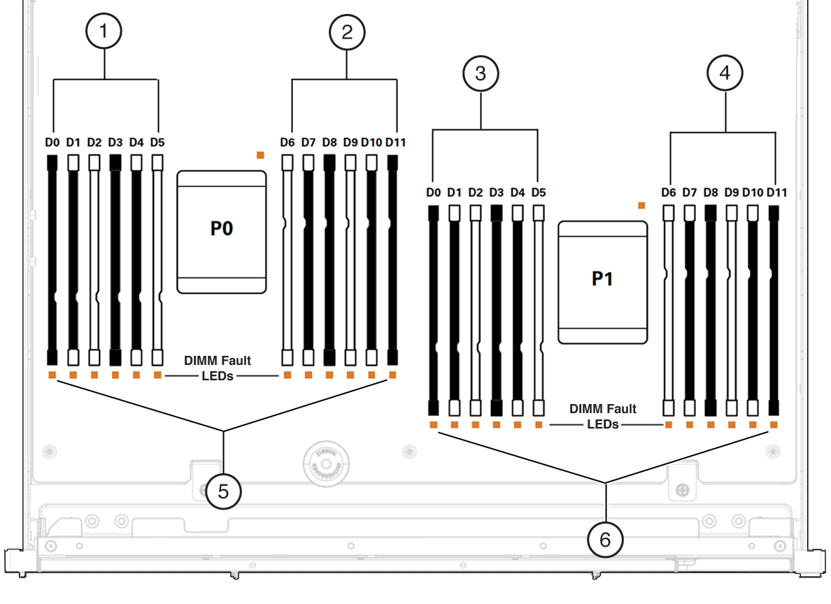
DIMM Configuration
In this illustration of the DIMM slots, the Oracle ILOM legacy targets for the DIMMs are provided across the top, and the Oracle ILOM /System targets for the DIMMs are provided across the bottom.
For example, the slot on the far left has the Oracle ILOM legacy target of /SYS/MB/P1/D0. This same slot has the Oracle ILOM /System target of /System/Memory/DIMMs/DIMM_0.
Note - This illustration shows the DIMM slots for the dual-processor configuration. With the single-processor configuration, the DIMM slots on P1 are not functional, and must be filled with filler panels.

|
When you add or remove DIMMs to the motherboard, follow these guidelines:
-
You can configure an odd number of DIMMs, however an equally-balanced even number of DIMMs provides better performance.
-
When you add DIMMs in pairs, the pair should be of the same part number.
-
If you are mixing DIMM capacities, install the largest capacities first, then consecutively smaller capacities.
-
If a slot is empty, install a DIMM filler. With the single-processor configuration, all DIMM slots on P1 must be filled with filler panels.

Caution - Overheating hazard. There must be no empty DIMM slots.
-
Populate the DIMMs in the order described in DIMM Population Guidelines for Dual-Processor Servers